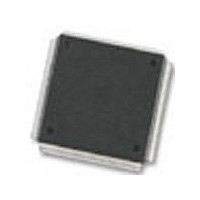
MC68376BAMFT20 Freescale Semiconductor, MC68376BAMFT20 Datasheet - Page 251

MC68376BAMFT20
Manufacturer Part Number
MC68376BAMFT20
Description
Manufacturer
Freescale Semiconductor
Datasheet
1.MC68376BAMFT20.pdf
(434 pages)
Specifications of MC68376BAMFT20
Cpu Family
68K/M683xx
Device Core
ColdFire
Device Core Size
32b
Frequency (max)
20MHz
Interface Type
QSPI/SCI
Program Memory Type
ROM
Program Memory Size
8KB
Total Internal Ram Size
7.5KB
# I/os (max)
18
Number Of Timers - General Purpose
2
Operating Supply Voltage (typ)
5V
Operating Supply Voltage (max)
5.25V
Operating Supply Voltage (min)
4.75V
On-chip Adc
16-chx10-bit
Instruction Set Architecture
RISC
Operating Temp Range
-40C to 125C
Operating Temperature Classification
Automotive
Mounting
Surface Mount
Pin Count
160
Package Type
PQFP
Lead Free Status / Rohs Status
Not Compliant
Available stocks
Company
Part Number
Manufacturer
Quantity
Price
Company:
Part Number:
MC68376BAMFT20
Manufacturer:
FREESCAL
Quantity:
245
- Current page: 251 of 434
- Download datasheet (7Mb)
11.6.2.4 Host Service Registers
11.6.2.5 Channel Priority Registers
11.6.3 Development Support and Test Registers
MC68336/376
USER’S MANUAL
The host service request field selects the type of host service request for the time func-
tion selected on a given channel. The meaning of the host service request bits is de-
termined by time function microcode. Refer to the TPU Reference Manual (TPURM/
AD) and the Motorola TPU Literature Package (TPULITPAK/D) for more information.
A host service request field of %00 signals the CPU that service is completed and that
there are no further pending host service requests. The host can request service on a
channel by writing the corresponding host service request field to one of three non-
zero states. It is imperative for the CPU to monitor the host service request register
and wait until the TPU clears the service request for a channel before changing any
parameters or issuing a new service request to the channel.
The channel priority registers (CPR1, CPR2) assign one of three priority levels to a
channel or disable the channel. Table 11-4 indicates the number of time slots guaran-
teed for each channel priority encoding.
These registers are used for custom microcode development or for factory test. De-
scribing the use of these registers is beyond the scope of this manual. Register de-
scriptions are provided in D.8 Time Processor Unit (TPU). Refer to the TPU
Reference Manual (TPURM/AD) for more information.
CHX[1:0]
00
01
10
11
Table 11-4 Channel Priority Encodings
TIME PROCESSOR UNIT
Disabled
Service
Middle
High
Low
Guaranteed Time Slots
1 out of 7
2 out of 7
4 out of 7
—
MOTOROLA
11-17
Related parts for MC68376BAMFT20
Image
Part Number
Description
Manufacturer
Datasheet
Request
R
Part Number:
Description:
Manufacturer:
Freescale Semiconductor, Inc
Datasheet:
Part Number:
Description:
Manufacturer:
Freescale Semiconductor, Inc
Datasheet:
Part Number:
Description:
Manufacturer:
Freescale Semiconductor, Inc
Datasheet:
Part Number:
Description:
Manufacturer:
Freescale Semiconductor, Inc
Datasheet:
Part Number:
Description:
Manufacturer:
Freescale Semiconductor, Inc
Datasheet:
Part Number:
Description:
Manufacturer:
Freescale Semiconductor, Inc
Datasheet:
Part Number:
Description:
Manufacturer:
Freescale Semiconductor, Inc
Datasheet:
Part Number:
Description:
Manufacturer:
Freescale Semiconductor, Inc
Datasheet:
Part Number:
Description:
Manufacturer:
Freescale Semiconductor, Inc
Datasheet:
Part Number:
Description:
Manufacturer:
Freescale Semiconductor, Inc
Datasheet:
Part Number:
Description:
Manufacturer:
Freescale Semiconductor, Inc
Datasheet:
Part Number:
Description:
Manufacturer:
Freescale Semiconductor, Inc
Datasheet:
Part Number:
Description:
Manufacturer:
Freescale Semiconductor, Inc
Datasheet:
Part Number:
Description:
Manufacturer:
Freescale Semiconductor, Inc
Datasheet:
Part Number:
Description:
Manufacturer:
Freescale Semiconductor, Inc
Datasheet:


