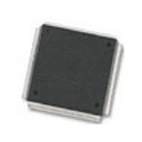
MC68376BAMFT20 Freescale Semiconductor, MC68376BAMFT20 Datasheet - Page 66

MC68376BAMFT20
Manufacturer Part Number
MC68376BAMFT20
Description
Manufacturer
Freescale Semiconductor
Datasheet
1.MC68376BAMFT20.pdf
(434 pages)
Specifications of MC68376BAMFT20
Cpu Family
68K/M683xx
Device Core
ColdFire
Device Core Size
32b
Frequency (max)
20MHz
Interface Type
QSPI/SCI
Program Memory Type
ROM
Program Memory Size
8KB
Total Internal Ram Size
7.5KB
# I/os (max)
18
Number Of Timers - General Purpose
2
Operating Supply Voltage (typ)
5V
Operating Supply Voltage (max)
5.25V
Operating Supply Voltage (min)
4.75V
On-chip Adc
16-chx10-bit
Instruction Set Architecture
RISC
Operating Temp Range
-40C to 125C
Operating Temperature Classification
Automotive
Mounting
Surface Mount
Pin Count
160
Package Type
PQFP
Lead Free Status / Rohs Status
Not Compliant
Available stocks
Company
Part Number
Manufacturer
Quantity
Price
Company:
Part Number:
MC68376BAMFT20
Manufacturer:
FREESCAL
Quantity:
245
- Current page: 66 of 434
- Download datasheet (7Mb)
4.8.1 M68000 Family Compatibility
4.8.2 Special Control Instructions
4.8.2.1 Low-Power Stop (LPSTOP)
4.8.2.2 Table Lookup and Interpolate (TBL)
4-14
MOTOROLA
NOTES:
TBLSN/TBLUN
It is the philosophy of the M68000 family that all user-mode programs can execute un-
changed on future derivatives of the M68000 family, and supervisor-mode programs
and exception handlers should require only minimal alteration.
The CPU32 can be thought of as an intermediate member of the M68000 Family. Ob-
ject code from an MC68000 or MC68010 may be executed on the CPU32. Many of the
instruction and addressing mode extensions of the MC68020 are also supported. Re-
fer to the CPU32 Reference Manual (CPU32RM/AD) for a detailed comparison of the
CPU32 and MC68020 instruction set.
Low-power stop (LPSTOP) and table lookup and interpolate (TBL) instructions have
been added to the MC68000 instruction set for use in controller applications.
In applications where power consumption is a consideration, the CPU32 forces the de-
vice into a low-power standby mode when immediate processing is not required. The
low-power stop mode is entered by executing the LPSTOP instruction. The processor
remains in this mode until a user-specified (or higher) interrupt level or reset occurs.
To maximize throughput for real-time applications, reference data is often precalculat-
ed and stored in memory for quick access. Storage of many data points can require
an inordinate amount of memory. The table lookup instruction requires that only a
sample of data points be stored, reducing memory requirements. The TBL instruction
recovers intermediate values using linear interpolation. Results can be rounded with a
round-to-nearest algorithm.
1. Privileged instruction.
TRAPcc
TRAPV
TRAP
UNLK
TST
Table 4-2 Instruction Set Summary (Continued)
Dym : Dyn, Dn
<ea>, Dn
#<data>
#<data>
none
none
<ea>
An
CENTRAL PROCESSOR UNIT
8, 16, 32
8, 16, 32
16, 32
none
none
none
32
Dyn
(Temp
Dym
SSP
SSP
vector address
If cc true, then TRAP exception
If V set, then overflow TRAP exception
Source
An
SP; (SP)
Dym
2
4
Temp
Dn [7 : 0]) / 256
0, to set condition codes
SSP; format/vector offset
SSP; PC
Temp
Dn
PC
An, SP
(SSP); SR
Temp
4
SP
USER’S MANUAL
(SSP);
MC68336/376
(SSP);
Related parts for MC68376BAMFT20
Image
Part Number
Description
Manufacturer
Datasheet
Request
R
Part Number:
Description:
Manufacturer:
Freescale Semiconductor, Inc
Datasheet:
Part Number:
Description:
Manufacturer:
Freescale Semiconductor, Inc
Datasheet:
Part Number:
Description:
Manufacturer:
Freescale Semiconductor, Inc
Datasheet:
Part Number:
Description:
Manufacturer:
Freescale Semiconductor, Inc
Datasheet:
Part Number:
Description:
Manufacturer:
Freescale Semiconductor, Inc
Datasheet:
Part Number:
Description:
Manufacturer:
Freescale Semiconductor, Inc
Datasheet:
Part Number:
Description:
Manufacturer:
Freescale Semiconductor, Inc
Datasheet:
Part Number:
Description:
Manufacturer:
Freescale Semiconductor, Inc
Datasheet:
Part Number:
Description:
Manufacturer:
Freescale Semiconductor, Inc
Datasheet:
Part Number:
Description:
Manufacturer:
Freescale Semiconductor, Inc
Datasheet:
Part Number:
Description:
Manufacturer:
Freescale Semiconductor, Inc
Datasheet:
Part Number:
Description:
Manufacturer:
Freescale Semiconductor, Inc
Datasheet:
Part Number:
Description:
Manufacturer:
Freescale Semiconductor, Inc
Datasheet:
Part Number:
Description:
Manufacturer:
Freescale Semiconductor, Inc
Datasheet:
Part Number:
Description:
Manufacturer:
Freescale Semiconductor, Inc
Datasheet:


