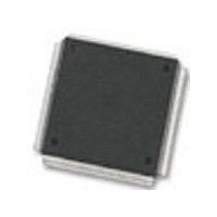
MC68376BAMFT20 Freescale Semiconductor, MC68376BAMFT20 Datasheet - Page 18

MC68376BAMFT20
Manufacturer Part Number
MC68376BAMFT20
Description
Manufacturer
Freescale Semiconductor
Datasheet
1.MC68376BAMFT20.pdf
(434 pages)
Specifications of MC68376BAMFT20
Cpu Family
68K/M683xx
Device Core
ColdFire
Device Core Size
32b
Frequency (max)
20MHz
Interface Type
QSPI/SCI
Program Memory Type
ROM
Program Memory Size
8KB
Total Internal Ram Size
7.5KB
# I/os (max)
18
Number Of Timers - General Purpose
2
Operating Supply Voltage (typ)
5V
Operating Supply Voltage (max)
5.25V
Operating Supply Voltage (min)
4.75V
On-chip Adc
16-chx10-bit
Instruction Set Architecture
RISC
Operating Temp Range
-40C to 125C
Operating Temperature Classification
Automotive
Mounting
Surface Mount
Pin Count
160
Package Type
PQFP
Lead Free Status / Rohs Status
Not Compliant
Available stocks
Company
Part Number
Manufacturer
Quantity
Price
Company:
Part Number:
MC68376BAMFT20
Manufacturer:
FREESCAL
Quantity:
245
- Current page: 18 of 434
- Download datasheet (7Mb)
Figure
8-1
8-2
8-3
8-4
8-5
8-6
8-7
8-8
8-9
8-10
8-11
9-1
9-2
9-3
9-4
9-5
9-6
9-7
9-8
9-9
9-10
9-11
10-1
10-2
10-3
10-4
10-5
10-6
11-1
11-2
11-3
13-1
13-2
13-3
13-4
13-5
A-1
A-2
A-3
A-4
A-5
xviii
MOTOROLA
QADC Block Diagram ..................................................................................... 8-1
QADC Input and Output Signals .................................................................... 8-3
Example of External Multiplexing ................................................................. 8-11
QADC Module Block Diagram ...................................................................... 8-13
Conversion Timing ....................................................................................... 8-14
Bypass Mode Conversion Timing ................................................................. 8-15
QADC Queue Operation with Pause ............................................................ 8-18
QADC Clock Subsystem Functions .............................................................. 8-24
QADC Clock Programmability Examples ..................................................... 8-26
QADC Conversion Queue Operation ........................................................... 8-29
QADC Interrupt Vector Format ..................................................................... 8-33
QSM Block Diagram ....................................................................................... 9-1
QSPI Block Diagram ...................................................................................... 9-5
QSPI RAM ...................................................................................................... 9-7
Flowchart of QSPI Initialization Operation .................................................... 9-10
Flowchart of QSPI Master Operation (Part 1) .............................................. 9-11
Flowchart of QSPI Master Operation (Part 2) .............................................. 9-12
Flowchart of QSPI Master Operation (Part 3) .............................................. 9-13
Flowchart of QSPI Slave Operation (Part 1) ................................................ 9-14
Flowchart of QSPI Slave Operation (Part 2) ................................................ 9-15
SCI Transmitter Block Diagram .................................................................... 9-22
SCI Receiver Block Diagram ........................................................................ 9-23
CTM4 Block Diagram ................................................................................... 10-1
CPSM Block Diagram ................................................................................... 10-4
FCSM Block Diagram ................................................................................... 10-5
MCSM Block Diagram .................................................................................. 10-8
DASM Block Diagram ................................................................................. 10-11
Pulse-Width Modulation Submodule Block Diagram .................................. 10-13
TPU Block Diagram ...................................................................................... 11-1
TCR1 Prescaler Control ............................................................................. 11-14
TCR2 Prescaler Control ............................................................................. 11-14
TouCAN Block Diagram ............................................................................... 13-1
Typical CAN Network ................................................................................... 13-2
Extended ID Message Buffer Structure ........................................................ 13-3
Standard ID Message Buffer Structure ........................................................ 13-4
TouCAN Interrupt Vector Generation ......................................................... 13-19
CLKOUT Output Timing Diagram ................................................................. A-10
External Clock Input Timing Diagram ........................................................... A-10
ECLK Output Timing Diagram ...................................................................... A-10
Read Cycle Timing Diagram ........................................................................ A-11
Write Cycle Timing Diagram ......................................................................... A-12
LIST OF ILLUSTRATIONS
(Continued)
Title
USER’S MANUAL
MC68336/376
Page
Related parts for MC68376BAMFT20
Image
Part Number
Description
Manufacturer
Datasheet
Request
R
Part Number:
Description:
Manufacturer:
Freescale Semiconductor, Inc
Datasheet:
Part Number:
Description:
Manufacturer:
Freescale Semiconductor, Inc
Datasheet:
Part Number:
Description:
Manufacturer:
Freescale Semiconductor, Inc
Datasheet:
Part Number:
Description:
Manufacturer:
Freescale Semiconductor, Inc
Datasheet:
Part Number:
Description:
Manufacturer:
Freescale Semiconductor, Inc
Datasheet:
Part Number:
Description:
Manufacturer:
Freescale Semiconductor, Inc
Datasheet:
Part Number:
Description:
Manufacturer:
Freescale Semiconductor, Inc
Datasheet:
Part Number:
Description:
Manufacturer:
Freescale Semiconductor, Inc
Datasheet:
Part Number:
Description:
Manufacturer:
Freescale Semiconductor, Inc
Datasheet:
Part Number:
Description:
Manufacturer:
Freescale Semiconductor, Inc
Datasheet:
Part Number:
Description:
Manufacturer:
Freescale Semiconductor, Inc
Datasheet:
Part Number:
Description:
Manufacturer:
Freescale Semiconductor, Inc
Datasheet:
Part Number:
Description:
Manufacturer:
Freescale Semiconductor, Inc
Datasheet:
Part Number:
Description:
Manufacturer:
Freescale Semiconductor, Inc
Datasheet:
Part Number:
Description:
Manufacturer:
Freescale Semiconductor, Inc
Datasheet:


