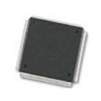
MC68376BAMFT20 Freescale Semiconductor, MC68376BAMFT20 Datasheet - Page 234

MC68376BAMFT20
Manufacturer Part Number
MC68376BAMFT20
Description
Manufacturer
Freescale Semiconductor
Datasheet
1.MC68376BAMFT20.pdf
(434 pages)
Specifications of MC68376BAMFT20
Cpu Family
68K/M683xx
Device Core
ColdFire
Device Core Size
32b
Frequency (max)
20MHz
Interface Type
QSPI/SCI
Program Memory Type
ROM
Program Memory Size
8KB
Total Internal Ram Size
7.5KB
# I/os (max)
18
Number Of Timers - General Purpose
2
Operating Supply Voltage (typ)
5V
Operating Supply Voltage (max)
5.25V
Operating Supply Voltage (min)
4.75V
On-chip Adc
16-chx10-bit
Instruction Set Architecture
RISC
Operating Temp Range
-40C to 125C
Operating Temperature Classification
Automotive
Mounting
Surface Mount
Pin Count
160
Package Type
PQFP
Lead Free Status / Rohs Status
Not Compliant
Available stocks
Company
Part Number
Manufacturer
Quantity
Price
Company:
Part Number:
MC68376BAMFT20
Manufacturer:
FREESCAL
Quantity:
245
- Current page: 234 of 434
- Download datasheet (7Mb)
10.10 CTM4 Interrupts
10-18
MOTOROLA
D.7.14 PWM Status/Interrupt/Control Register, D.7.15 PWM Period Register,
D.7.16 PWM Pulse Width Register, and D.7.17 PWM Counter Register for informa-
tion concerning PWMSM register and bit descriptions.
The CTM4 is able to generate as many as eleven requests for interrupt service. Each
submodule capable of requesting an interrupt can do so on any of seven levels. Sub-
modules that can request interrupt service have a 3-bit level number and a 1-bit arbi-
tration number that is user-initialized.
The 3-bit level number selects which of seven interrupt signals on the IMB are driven
by that submodule to generate an interrupt request. Of the four priority bits provided
by the IMB to the CTM4 for interrupt arbitration, one of them comes from the chosen
submodule, and the BIUSM provides the other three. Thus, the CTM4 can respond
with two of the 15 possible arbitration numbers.
During the IMB arbitration process, the BIUSM manages the separate arbitration
among the CTM4 submodules to determine which submodule should respond. The
CTM4 has a fixed hardware prioritization scheme for all submodules. When two or
more submodules have an interrupt request pending at the level being arbitrated on
the IMB, the submodule with the lowest number (also the lowest status/interrupt/con-
trol register address) is given the highest priority to respond.
If the CTM4 wins arbitration, it responds with a vector number generated by concate-
nating VECT[7:6] in BIUMCR and the six low-order bits specified by the number of the
submodule requesting service. Table 10-7 shows the allocation of CTM4 submodule
numbers and interrupt vector numbers.
Table 10-7 CTM4 Interrupt Priority and Vector/Pin Allocation
NOTES:
1. Y = M111, where M is the state of the MM bit in SIMCR (Y = $7 or $F).
2. “xx” represents VECT[7:6] in the BIUSM module configuration register.
Submodule
MCSM11
DASM10
FCSM12
MCSM2
PWSM5
PWSM6
PWSM7
PWSM8
DASM3
DASM4
DASM9
BIUSM
CPSM
Name
CONFIGURABLE TIMER MODULE 4
Submodule
Number
10
11
12
0
1
2
3
4
5
6
7
8
9
Submodule Base
$YFF400
Address
$YFF408
$YFF410
$YFF418
$YFF420
$YFF428
$YFF430
$YFF438
$YFF440
$YFF448
$YFF450
$YFF458
$YFF460
1
Submodule Binary
Vector Number
xx000010
xx000011
xx000100
xx000101
xx000110
xx000111
xx001000
xx001001
xx001010
xx001011
xx001100
None
None
2
USER’S MANUAL
MC68336/376
Related parts for MC68376BAMFT20
Image
Part Number
Description
Manufacturer
Datasheet
Request
R
Part Number:
Description:
Manufacturer:
Freescale Semiconductor, Inc
Datasheet:
Part Number:
Description:
Manufacturer:
Freescale Semiconductor, Inc
Datasheet:
Part Number:
Description:
Manufacturer:
Freescale Semiconductor, Inc
Datasheet:
Part Number:
Description:
Manufacturer:
Freescale Semiconductor, Inc
Datasheet:
Part Number:
Description:
Manufacturer:
Freescale Semiconductor, Inc
Datasheet:
Part Number:
Description:
Manufacturer:
Freescale Semiconductor, Inc
Datasheet:
Part Number:
Description:
Manufacturer:
Freescale Semiconductor, Inc
Datasheet:
Part Number:
Description:
Manufacturer:
Freescale Semiconductor, Inc
Datasheet:
Part Number:
Description:
Manufacturer:
Freescale Semiconductor, Inc
Datasheet:
Part Number:
Description:
Manufacturer:
Freescale Semiconductor, Inc
Datasheet:
Part Number:
Description:
Manufacturer:
Freescale Semiconductor, Inc
Datasheet:
Part Number:
Description:
Manufacturer:
Freescale Semiconductor, Inc
Datasheet:
Part Number:
Description:
Manufacturer:
Freescale Semiconductor, Inc
Datasheet:
Part Number:
Description:
Manufacturer:
Freescale Semiconductor, Inc
Datasheet:
Part Number:
Description:
Manufacturer:
Freescale Semiconductor, Inc
Datasheet:


