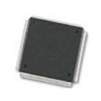
MC68376BAMFT20 Freescale Semiconductor, MC68376BAMFT20 Datasheet - Page 219

MC68376BAMFT20
Manufacturer Part Number
MC68376BAMFT20
Description
Manufacturer
Freescale Semiconductor
Datasheet
1.MC68376BAMFT20.pdf
(434 pages)
Specifications of MC68376BAMFT20
Cpu Family
68K/M683xx
Device Core
ColdFire
Device Core Size
32b
Frequency (max)
20MHz
Interface Type
QSPI/SCI
Program Memory Type
ROM
Program Memory Size
8KB
Total Internal Ram Size
7.5KB
# I/os (max)
18
Number Of Timers - General Purpose
2
Operating Supply Voltage (typ)
5V
Operating Supply Voltage (max)
5.25V
Operating Supply Voltage (min)
4.75V
On-chip Adc
16-chx10-bit
Instruction Set Architecture
RISC
Operating Temp Range
-40C to 125C
Operating Temperature Classification
Automotive
Mounting
Surface Mount
Pin Count
160
Package Type
PQFP
Lead Free Status / Rohs Status
Not Compliant
Available stocks
Company
Part Number
Manufacturer
Quantity
Price
Company:
Part Number:
MC68376BAMFT20
Manufacturer:
FREESCAL
Quantity:
245
- Current page: 219 of 434
- Download datasheet (7Mb)
10.4 Bus Interface Unit Submodule (BIUSM)
10.4.1 STOP Effect On the BIUSM
10.4.2 Freeze Effect On the BIUSM
MC68336/376
USER’S MANUAL
In the CTM4, TBB2 is global and accessible to every submodule. TBB1 and TBB4 are
split to form two local time base buses. Table 10-1 shows which time base buses are
available to each CTM4 submodule.
Each PWMSM has an independent 16-bit counter and 8-bit prescaler clocked by the
PCLK1 signal, which is generated by the CPSM. The PWMSMs are not connected to
any of the time base buses. Refer to 10.9 Pulse-Width Modulation Submodule
(PWMSM) for more information.
The BIUSM connects the SMB to the IMB and allows the CTM4 submodules to com-
municate with the CPU32. The BIUSM also communicates CTM4 submodule interrupt
requests to the IMB, and transfers the interrupt level, arbitration number and vector
number to the CPU32 during the interrupt acknowledge cycle.
When the CPU32 STOP instruction is executed, only the CPU32 is stopped; the CTM4
continues to operate as normal.
CTM4 response to assertion of the IMB FREEZE signal is controlled by the FRZ bit in
the BIUSM configuration register (BIUMCR). Since the BIUSM propagates FREEZE
to the CTM4 submodules via the SMB, the setting of FRZ affects all CTM4 submod-
ules.
If the IMB FREEZE signal is asserted and FRZ = 1, all CTM4 submodules freeze. The
following conditions apply when the CTM4 is frozen:
Submodule
MCSM 11
FCSM 12
DASM10
DASM9
• All submodule registers can still be accessed.
• The CPSM, FCSM, MCSM, and PWMSM counters stop counting.
• The IN status bit still reflects the state of the FCSM external clock input pin.
• The IN2 status bit still reflects the state of the MCSM external clock input pin, and
• DASM capture and compare functions are disabled.
• The DASM IN status bit still reflects the state of its associated pin in the DIS,
• When configured for OCB, OCAB, or OPWM modes, the state of the DASM
the IN1 status bit still reflects the state of the MCSM modulus load input pin.
IPWM, IPM, and IC modes. In the OCB, OCAB, and OPWM modes, IN reflects
the state of the DASM output flip flop.
Global Bus A
Global/Local Time Base
TBB1
TBB1
TBB1
TBB1
Table 10-1 CTM4 Time Base Bus Allocation
Bus Allocation
CONFIGURABLE TIMER MODULE 4
Global Bus B
TBB2
TBB2
TBB2
TBB2
Submodule
MCSM 2
DASM 3
DASM 4
Global Bus A
Global/Local Time Base
TBB4
TBB4
TBB4
Bus Allocation
Global Bus B
MOTOROLA
TBB2
TBB2
TBB2
10-3
Related parts for MC68376BAMFT20
Image
Part Number
Description
Manufacturer
Datasheet
Request
R
Part Number:
Description:
Manufacturer:
Freescale Semiconductor, Inc
Datasheet:
Part Number:
Description:
Manufacturer:
Freescale Semiconductor, Inc
Datasheet:
Part Number:
Description:
Manufacturer:
Freescale Semiconductor, Inc
Datasheet:
Part Number:
Description:
Manufacturer:
Freescale Semiconductor, Inc
Datasheet:
Part Number:
Description:
Manufacturer:
Freescale Semiconductor, Inc
Datasheet:
Part Number:
Description:
Manufacturer:
Freescale Semiconductor, Inc
Datasheet:
Part Number:
Description:
Manufacturer:
Freescale Semiconductor, Inc
Datasheet:
Part Number:
Description:
Manufacturer:
Freescale Semiconductor, Inc
Datasheet:
Part Number:
Description:
Manufacturer:
Freescale Semiconductor, Inc
Datasheet:
Part Number:
Description:
Manufacturer:
Freescale Semiconductor, Inc
Datasheet:
Part Number:
Description:
Manufacturer:
Freescale Semiconductor, Inc
Datasheet:
Part Number:
Description:
Manufacturer:
Freescale Semiconductor, Inc
Datasheet:
Part Number:
Description:
Manufacturer:
Freescale Semiconductor, Inc
Datasheet:
Part Number:
Description:
Manufacturer:
Freescale Semiconductor, Inc
Datasheet:
Part Number:
Description:
Manufacturer:
Freescale Semiconductor, Inc
Datasheet:


