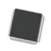
MC68376BAMFT20 Freescale Semiconductor, MC68376BAMFT20 Datasheet - Page 135

MC68376BAMFT20
Manufacturer Part Number
MC68376BAMFT20
Description
Manufacturer
Freescale Semiconductor
Datasheet
1.MC68376BAMFT20.pdf
(434 pages)
Specifications of MC68376BAMFT20
Cpu Family
68K/M683xx
Device Core
ColdFire
Device Core Size
32b
Frequency (max)
20MHz
Interface Type
QSPI/SCI
Program Memory Type
ROM
Program Memory Size
8KB
Total Internal Ram Size
7.5KB
# I/os (max)
18
Number Of Timers - General Purpose
2
Operating Supply Voltage (typ)
5V
Operating Supply Voltage (max)
5.25V
Operating Supply Voltage (min)
4.75V
On-chip Adc
16-chx10-bit
Instruction Set Architecture
RISC
Operating Temp Range
-40C to 125C
Operating Temperature Classification
Automotive
Mounting
Surface Mount
Pin Count
160
Package Type
PQFP
Lead Free Status / Rohs Status
Not Compliant
Available stocks
Company
Part Number
Manufacturer
Quantity
Price
Company:
Part Number:
MC68376BAMFT20
Manufacturer:
FREESCAL
Quantity:
245
- Current page: 135 of 434
- Download datasheet (7Mb)
5.9.1 Chip-Select Registers
5.9.1.1 Chip-Select Pin Assignment Registers
MC68336/376
USER’S MANUAL
Each chip-select pin can have one or more functions. Chip-select pin assignment reg-
isters CSPAR[0:1] determine functions of the pins. Pin assignment registers also de-
termine port size (8- or 16-bit) for dynamic bus allocation. A pin data register (PORTC)
latches data for chip-select pins that are used for discrete output.
Blocks of addresses are assigned to each chip-select function. Block sizes of two
Kbytes to one Mbyte can be selected by writing values to the appropriate base address
register (CSBAR[0:10] and CSBARBT). Multiple chip-selects assigned to the same
block of addresses must have the same number of wait states. The base address reg-
ister for a chip-select line should be written to a value that is an exact integer multiple
of both the block size and the size of the memory device being selected.
Chip-select option registers (CSORBT and CSOR[0:10]) determine timing of and con-
ditions for assertion of chip-select signals. Eight parameters, including operating
mode, access size, synchronization, and wait state insertion can be specified.
Initialization software usually resides in a peripheral memory device controlled by the
chip-select circuits. A set of special chip-select functions and registers (CSORBT and
CSBARBT) is provided to support bootstrap operation.
Comprehensive address maps and register diagrams are provided in APPENDIX D
REGISTER SUMMARY.
The pin assignment registers contain twelve 2-bit fields that determine the functions of
the chip-select pins. Each pin has two or three possible functions, as shown in Table
5-18.
Table 5-19 shows pin assignment field encoding. Pins that have no discrete output
function must not use the %00 encoding as this will cause the alternate function to be
selected. For instance, %00 for CS0/BR will cause the pin to perform the BR function.
Chip-Select
CSBOOT
CS10
Table 5-18 Chip-Select Pin Functions
CS0
CS1
CS2
CS3
CS4
CS5
CS6
CS7
CS8
CS9
SYSTEM INTEGRATION MODULE
Alternate
Function
CSBOOT
ADDR19
ADDR20
ADDR21
ADDR22
ADDR23
BGACK
FC0
FC1
FC2
BG
BR
Discrete
Output
ECLK
PC0
PC1
PC2
PC3
PC4
PC5
PC6
—
—
—
—
MOTOROLA
5-57
Related parts for MC68376BAMFT20
Image
Part Number
Description
Manufacturer
Datasheet
Request
R
Part Number:
Description:
Manufacturer:
Freescale Semiconductor, Inc
Datasheet:
Part Number:
Description:
Manufacturer:
Freescale Semiconductor, Inc
Datasheet:
Part Number:
Description:
Manufacturer:
Freescale Semiconductor, Inc
Datasheet:
Part Number:
Description:
Manufacturer:
Freescale Semiconductor, Inc
Datasheet:
Part Number:
Description:
Manufacturer:
Freescale Semiconductor, Inc
Datasheet:
Part Number:
Description:
Manufacturer:
Freescale Semiconductor, Inc
Datasheet:
Part Number:
Description:
Manufacturer:
Freescale Semiconductor, Inc
Datasheet:
Part Number:
Description:
Manufacturer:
Freescale Semiconductor, Inc
Datasheet:
Part Number:
Description:
Manufacturer:
Freescale Semiconductor, Inc
Datasheet:
Part Number:
Description:
Manufacturer:
Freescale Semiconductor, Inc
Datasheet:
Part Number:
Description:
Manufacturer:
Freescale Semiconductor, Inc
Datasheet:
Part Number:
Description:
Manufacturer:
Freescale Semiconductor, Inc
Datasheet:
Part Number:
Description:
Manufacturer:
Freescale Semiconductor, Inc
Datasheet:
Part Number:
Description:
Manufacturer:
Freescale Semiconductor, Inc
Datasheet:
Part Number:
Description:
Manufacturer:
Freescale Semiconductor, Inc
Datasheet:


