R0K561622S000BE Renesas Electronics America, R0K561622S000BE Datasheet - Page 22
R0K561622S000BE
Manufacturer Part Number
R0K561622S000BE
Description
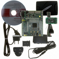
KIT STARTER FOR H8SX/1622
Manufacturer
Renesas Electronics America
Series
Renesas Starter Kits (RSK)r
Type
MCUr
Specifications of R0K561622S000BE
Contents
Board, Cables, CD, Debugger, Power Supply
Silicon Manufacturer
Renesas
Features
Coding And Debugging, E10A Emulator, RS232 Serial Connection
Kit Contents
Board
Silicon Family Name
H8SX/1622F
Silicon Core Number
R5F61622N50LGV
Lead Free Status / RoHS Status
Lead free / RoHS Compliant
For Use With/related Products
H8SX/1622
Lead Free Status / RoHS Status
Lead free / RoHS Compliant, Lead free / RoHS Compliant


Section 15 Watchdog Timer (WDT) ................................................................. 589
15.1
15.2
15.3
15.4
15.5
15.6
Section 16 Serial Communication Interface (SCI)............................................ 601
16.1
16.2
16.3
Rev. 2.00 Sep. 16, 2009 Page xx of xxviii
14.8.4
14.8.5
14.8.6
14.8.7
14.8.8
14.8.9
Features............................................................................................................................. 589
Input/Output Pin ............................................................................................................... 590
Register Descriptions........................................................................................................ 591
15.3.1
15.3.2
15.3.3
Operation .......................................................................................................................... 594
15.4.1
15.4.2
Interrupt Source ................................................................................................................ 596
Usage Notes ...................................................................................................................... 597
15.6.1
15.6.2
15.6.3
15.6.4
15.6.5
15.6.6
15.6.7
Features............................................................................................................................. 601
Input/Output Pins.............................................................................................................. 603
Register Descriptions........................................................................................................ 604
16.3.1
16.3.2
16.3.3
16.3.4
16.3.5
16.3.6
16.3.7
16.3.8
16.3.9
Conflict between TCOR Write and Compare Match........................................ 584
Conflict between Compare Matches A and B................................................... 585
Switching of Internal Clocks and TCNT Operation ......................................... 585
Mode Setting with Cascaded Connection ......................................................... 587
Module Stop Function Setting .......................................................................... 587
Interrupts in Module Stop State ........................................................................ 587
Timer Counter (TCNT)..................................................................................... 591
Timer Control/Status Register (TCSR)............................................................. 591
Reset Control/Status Register (RSTCSR)......................................................... 593
Watchdog Timer Mode..................................................................................... 594
Interval Timer Mode......................................................................................... 596
Notes on Register Access ................................................................................. 597
Conflict between Timer Counter (TCNT) Write and Increment....................... 598
Changing Values of Bits CKS2 to CKS0.......................................................... 598
Switching between Watchdog Timer Mode and Interval Timer Mode............. 598
Internal Reset in Watchdog Timer Mode.......................................................... 599
System Reset by WDTOVF Signal................................................................... 599
Transition to Watchdog Timer Mode or Software Standby Mode.................... 599
Receive Shift Register (RSR) ........................................................................... 606
Receive Data Register (RDR)........................................................................... 606
Transmit Data Register (TDR).......................................................................... 606
Transmit Shift Register (TSR) .......................................................................... 607
Serial Mode Register (SMR) ............................................................................ 607
Serial Control Register (SCR) .......................................................................... 610
Serial Status Register (SSR) ............................................................................. 616
Smart Card Mode Register (SCMR)................................................................. 624
Bit Rate Register (BRR) ................................................................................... 625
Related parts for R0K561622S000BE
Image
Part Number
Description
Manufacturer
Datasheet
Request
R

Part Number:
Description:
KIT STARTER FOR M16C/29
Manufacturer:
Renesas Electronics America
Datasheet:

Part Number:
Description:
KIT STARTER FOR R8C/2D
Manufacturer:
Renesas Electronics America
Datasheet:

Part Number:
Description:
R0K33062P STARTER KIT
Manufacturer:
Renesas Electronics America
Datasheet:

Part Number:
Description:
KIT STARTER FOR R8C/23 E8A
Manufacturer:
Renesas Electronics America
Datasheet:

Part Number:
Description:
KIT STARTER FOR R8C/25
Manufacturer:
Renesas Electronics America
Datasheet:

Part Number:
Description:
KIT STARTER H8S2456 SHARPE DSPLY
Manufacturer:
Renesas Electronics America
Datasheet:

Part Number:
Description:
KIT STARTER FOR R8C38C
Manufacturer:
Renesas Electronics America
Datasheet:

Part Number:
Description:
KIT STARTER FOR R8C35C
Manufacturer:
Renesas Electronics America
Datasheet:

Part Number:
Description:
KIT STARTER FOR R8CL3AC+LCD APPS
Manufacturer:
Renesas Electronics America
Datasheet:
Part Number:
Description:
KIT STARTER FOR RX610
Manufacturer:
Renesas Electronics America
Datasheet:

Part Number:
Description:
KIT STARTER FOR R32C/118
Manufacturer:
Renesas Electronics America
Datasheet:

Part Number:
Description:
KIT DEV RSK-R8C/26-29
Manufacturer:
Renesas Electronics America
Datasheet:

Part Number:
Description:
KIT STARTER FOR SH7124
Manufacturer:
Renesas Electronics America
Datasheet:

Part Number:
Description:
KIT DEV FOR SH7203
Manufacturer:
Renesas Electronics America
Datasheet:
Part Number:
Description:
KIT STARTER FOR R8C/18191A1B
Manufacturer:
Renesas Electronics America
Datasheet: