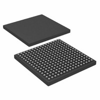
AD6636CBCZ Analog Devices Inc, AD6636CBCZ Datasheet - Page 24

AD6636CBCZ
Manufacturer Part Number
AD6636CBCZ
Description
IC DIGITAL DWNCONV 4CH 256CSPBGA
Manufacturer
Analog Devices Inc
Series
AD6636r
Datasheet
1.AD6636BCPCB.pdf
(80 pages)
Specifications of AD6636CBCZ
Rf Type
Cellular, CDMA2000, EDGE, GPRS, GSM
Number Of Mixers
1
Secondary Attributes
Down Converter
Current - Supply
450mA
Voltage - Supply
3 V ~ 3.6 V
Package / Case
256-CSPBGA
Brief Features
4/6 Independent Wideband Processing Channel, Quadrature Correction & DC Correction For Complex Input
Supply Voltage Range
1.7V To 1.9V
Operating Temperature Range
-40°C To +85°C
Ic Function
Digital Down Converter (DDC)
Rohs Compliant
Yes
Pin Count
256
Screening Level
Industrial
Package Type
CSPBGA
Lead Free Status / RoHS Status
Lead free / RoHS Compliant
Frequency
-
Gain
-
Noise Figure
-
Lead Free Status / Rohs Status
Compliant
Available stocks
Company
Part Number
Manufacturer
Quantity
Price
Company:
Part Number:
AD6636CBCZ
Manufacturer:
ADI
Quantity:
240
AD6636
Figure 26 is a block diagram of the peak detector logic. The
MSR contains the absolute magnitude of the peak detected by
the peak detector logic.
Mean Power Mode (Control Bits 01)
In this mode, the mean power of the input port signal is
integrated (by adding an accumulator) over a programmable
time period (given by AMPR) to give the mean power of the
input signal. This mode is set by programming Logic 1 in the
power monitor function select bits of the power monitor
control register for each individual input port. The 24-bit
AMPR, representing the period over which integration is
performed, must be programmed before activating this mode.
After enabling this mode, the value in the AMPR is loaded into
a monitor period timer, and the countdown is started
immediately. The 15-bit mean power of input signal is right-
shifted by nine bits to give 6-bit data. This 6-bit data is added to
the contents of a 24-bit holding register, thus performing an
accumulation. The integration continues until the monitor
period timer reaches a count of 1.
When the monitor period timer reaches a count of 1, the value
in the MSR is transferred to the power-monitor holding register
(after some formatting), which can be read through the
microport or the serial port. The monitor period timer is
reloaded with the value in the AMPR, and the countdown is
started. Also, the first input sample signal power is updated in
the MSR, and the accumulation continues with the subsequent
input samples. If the interrupt is enabled, an interrupt is
generated, and the interrupt status register is updated when the
AMPR reaches a count of 1. Figure 27 illustrates the mean
power-monitoring logic.
The value in the MSR is a floating-point number with 4 MSBs
and 20 LSBs. If the 4 MSBs are EXP and the 20 LSBs are MAG,
the value in dBFS can be decoded by
MEMORY
PORTS
FROM
FROM
INPUT
MAP
Mean Power = 10 log
PERIOD REGISTER
POWER MONITOR
Figure 26. ADC Input Peak Detector Block Diagram
LOAD
MAGNITUDE
REGISTER
STORAGE
COMPARE
A>B
CLEAR
LOAD
⎡
⎢
⎣
COUNTER
⎛
⎜
⎝
DOWN
MAG
2
20
⎞
⎟
⎠
POWER MONITOR
2
LOAD
−
IS COUNT = 1?
(
REGISTER
HOLDING
EXP
−
1
)
⎤
⎥
⎦
CONTROLLER
MEMORY
INTERRUPT
MAP
TO
TO
Rev. A | Page 24 of 80
Threshold Crossing Mode (Control Bits 10)
In this mode of operation, the magnitude of the input port
signal is monitored over a programmable time period (given by
AMPR) to count the number of times it crosses a certain
programmable threshold value. This mode is set by program-
ming Logic 1x (where x is a don’t care bit) in the power-monitor
function select bits of the power monitor control register for
each individual input port. Before activating this mode, the user
needs to program the 24-bit AMPR and the 10-bit upper
threshold register for each individual input port. The same
upper threshold register is used for both power monitoring and
gain control (see the ADC Gain Control section).
After entering this mode, the value in the AMPR is loaded into
a monitor period timer, and the countdown is started. The
magnitude of the input signal is compared to the upper
threshold register (programmed previously) on each input clock
cycle. If the input signal has magnitude greater than the upper
threshold register, then the MSR register is incremented by 1.
The initial value of the MSR is set to 0. This comparison and
increment of the MSR register continues until the monitor
period timer reaches a count of 1.
When the monitor period timer reaches a count of 1, the value
in the MSR is transferred to the power monitor holding register,
which can be read through the microport or the serial port. The
monitor period timer is reloaded with the value in the AMPR,
and the countdown is started. The MSR register is also cleared
to a value of 0. If interrupts are enabled, an interrupt is
generated, and the interrupt status register is updated when the
AMPR reaches a count of 1. Figure 28 illustrates the threshold
crossing logic. The value in the MSR is the number of samples
that have an amplitude greater than the threshold register.
MEMORY
MEMORY
MEMORY
PORTS
PORTS
FROM
FROM
INPUT
FROM
FROM
FROM
INPUT
MAP
MAP
MAP
Figure 27. ADC Input Mean Power-Monitoring Block Diagram
Figure 28. ADC Input Threshold Crossing Block Diagram
THRESHOLD
PERIOD REGISTER
PERIOD REGISTER
POWER MONITOR
REGISTER
POWER MONITOR
UPPER
A
ACCUMULATOR
COMPARE
A > B
B
CLEAR
LOAD
LOAD
COUNTER
CLEAR
COUNTER
DOWN
DOWN
COMPARE
A > B
POWER MONITOR
LOAD
IS COUNT = 1?
IS COUNT = 1?
REGISTER
HOLDING
POWER MONITOR
LOAD
REGISTER
HOLDING
CONTROLLER
MEMORY
CONTROLLER
INTERRUPT
INTERRUPT
MAP
TO
MEMORY
TO
TO
MAP
TO


