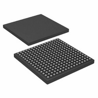
AD6636CBCZ Analog Devices Inc, AD6636CBCZ Datasheet - Page 31

AD6636CBCZ
Manufacturer Part Number
AD6636CBCZ
Description
IC DIGITAL DWNCONV 4CH 256CSPBGA
Manufacturer
Analog Devices Inc
Series
AD6636r
Datasheet
1.AD6636BCPCB.pdf
(80 pages)
Specifications of AD6636CBCZ
Rf Type
Cellular, CDMA2000, EDGE, GPRS, GSM
Number Of Mixers
1
Secondary Attributes
Down Converter
Current - Supply
450mA
Voltage - Supply
3 V ~ 3.6 V
Package / Case
256-CSPBGA
Brief Features
4/6 Independent Wideband Processing Channel, Quadrature Correction & DC Correction For Complex Input
Supply Voltage Range
1.7V To 1.9V
Operating Temperature Range
-40°C To +85°C
Ic Function
Digital Down Converter (DDC)
Rohs Compliant
Yes
Pin Count
256
Screening Level
Industrial
Package Type
CSPBGA
Lead Free Status / RoHS Status
Lead free / RoHS Compliant
Frequency
-
Gain
-
Noise Figure
-
Lead Free Status / Rohs Status
Compliant
Available stocks
Company
Part Number
Manufacturer
Quantity
Price
Company:
Part Number:
AD6636CBCZ
Manufacturer:
ADI
Quantity:
240
This filter runs at the same sample rate as the CIC filter output
rate and is given by
where:
f
M
The maximum input and output rates for this filter are
150 MHz.
Decimate-by-2, Half-Band Filter (HB1)
The next stage of the FIR-HB block is a decimate-by-2, half-
band filter. The 11-tap, symmetrical, fixed-coefficient HB1 filter
has low power consumption due to its polyphase implementa-
tion. The filter has 22 bits of input and output data with 10-bit
coefficients. Table 15 lists the coefficients of the half-band filter.
The normalized coefficients used in the implementation and
the 10-bit decimal equivalent value of the coefficients are also
listed. Other coefficients are 0s.
Table 15. Fixed Coefficients for HB1 Filter
Coefficient
Number
C1, C11
C3, C9
C5, C7
C6
Similar to the FIR1 filter, this filter can be used or bypassed.
Writing Logic 0 to the HB1 enable bit in the FIR-HB control
register bypasses this fixed-coefficient HB filter. The filter is
useful in certain filter configurations only and bypassing it for
other applications results in power savings. For example, it is
useful in narrow-band and wideband output applications in
which more filtering is required as compared to very wide
bandwidth applications in which a higher output rate may
prohibit the use of a decimating filter. The response of the filter
is shown in Figure 32.
The input sample rate of this filter is the same as the CIC filter
output rate and is given by
where:
f
M
in
in
CIC
CIC
is the input rate in to the channel.
is the input rate in to the channel.
f
f
is the decimation ratio in the CIC filter stage.
is the decimation ratio in the CIC filter stage.
FIR1
HB1
= f
= f
in
in
/M
/M
CIC
CIC
Normalized
Coefficient
+0.013671875
−0.103515625
+0.58984375
+1
Decimal Coefficient
(10-Bit)
+7
−53
+302
+512
Rev. A | Page 31 of 80
The filter has a maximum input sample rate of 150 MHz
and, when the filter is not bypassed, the maximum output rate
is 75 MHz.
The filter has a ripple of 0.0012 dB and rejection of 77 dB. For
an alias rejection of 77 dB, the alias-protected bandwidth is 14%
of the filter input sample rate. The bandwidth of the filter for a
ripple of 0.00075 dB is also the same as the alias-protected
bandwidth, due to the nature of half-band filters. The 3 dB
bandwidth of this filter is 44% of the filter input sample rate.
For example, if the sample rate into the filter is 50 MHz, then
the alias-protected bandwidth of the HB1 filter is 7 MHz. If the
bandwidth of the required carrier is greater than 7 MHz, then
HB1 may not be useful.
Figure 33. Composite Response of FIR1 and HB1 Filters to their Input Rate
–100
–110
–120
100
110
120
–10
–20
–30
–40
–50
–60
–70
–80
–90
10
20
30
40
50
60
70
80
90
Figure 32. HB1 Filter Response to the Input Rate of the Filter
0
0
0
0
HB1 RESPONSE
0.1
0.1
FRACTION OF HB1 INPUT SAMPLE RATE
FRACTION OF HB1 INPUT SAMPLE RATE
0.2
0.2
0.3
0.3
0.43
0.43
0.4
0.4
0.5
0.5
0.6
0.6
0.57
0.57
FIR1 + HB1 RESPONSE
0.7
0.7
0.8
0.8
0.9
0.9
AD6636
–107
–77


