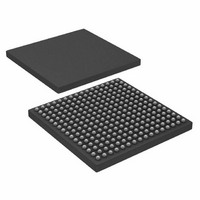
AD6636CBCZ Analog Devices Inc, AD6636CBCZ Datasheet - Page 42

AD6636CBCZ
Manufacturer Part Number
AD6636CBCZ
Description
IC DIGITAL DWNCONV 4CH 256CSPBGA
Manufacturer
Analog Devices Inc
Series
AD6636r
Datasheet
1.AD6636BCPCB.pdf
(80 pages)
Specifications of AD6636CBCZ
Rf Type
Cellular, CDMA2000, EDGE, GPRS, GSM
Number Of Mixers
1
Secondary Attributes
Down Converter
Current - Supply
450mA
Voltage - Supply
3 V ~ 3.6 V
Package / Case
256-CSPBGA
Brief Features
4/6 Independent Wideband Processing Channel, Quadrature Correction & DC Correction For Complex Input
Supply Voltage Range
1.7V To 1.9V
Operating Temperature Range
-40°C To +85°C
Ic Function
Digital Down Converter (DDC)
Rohs Compliant
Yes
Pin Count
256
Screening Level
Industrial
Package Type
CSPBGA
Lead Free Status / RoHS Status
Lead free / RoHS Compliant
Frequency
-
Gain
-
Noise Figure
-
Lead Free Status / Rohs Status
Compliant
Available stocks
Company
Part Number
Manufacturer
Quantity
Price
Company:
Part Number:
AD6636CBCZ
Manufacturer:
ADI
Quantity:
240
AD6636
The average and decimate operations are tied together and
implemented using a first-order CIC filter and FIFO registers.
Gain and bit growth are associated with CIC filters and depend
on the decimation ratio. To compensate for the gain associated
with these operations, attenuation scaling is provided before the
CIC filter.
This scaling operation accounts for the division associated with
the averaging operation as well as the traditional bit growth in
CIC filters. Because this scaling is implemented as a bit-shift
operation, only coarse scaling is possible. Fine scaling is
implemented as an offset in the request level, as explained later
in this section. The attenuation scaling S
from 0 to 14 using a 4-bit CIC scale word in the AGC average
samples register and is given by
where:
M
N
multiple of the decimation ratio (1, 2, 3, or 4).
For example, if a decimation ratio M
(decimation of 1,000 and averaging of 3,000 samples), then the
actual gain due to averaging and decimation is 3,000 or
69.54 dB (log
bit-shift operation, only multiples of 6.02 dB attenuations are
possible. S
way, S
compensate for the gain in the average and decimate sections
and, therefore, prevents overflows in the AGC loop. However, it
is also evident that the S
difference between gain due to CIC and attenuation provided
by scaling) of up to 6.02 dB. This error should be compensated
for in the request signal level, as explained later in this section.
A Base 2 logarithm is applied to the output from the average
and decimate section. These decimated power samples are
converted to rms signal samples by applying a square root
operation. This square root is implemented using a simple shift
operation in the logarithmic domain. The rms samples obtained
are subtracted from the request signal level R specified in the
AGC desired level register, leaving an error term to be
processed by the loop filter, G(z).
The user sets this programmable request signal level R accord-
ing to the output signal level that is desired. The request signal
level R is programmable from −0 dB to −23.99 dB in steps of
0.094 dB.
AVG
CIC
S
is the decimation ratio (1 to 4,096).
is the number of averaged samples programmed as a
CIC
CIC
= ceil [log
scaling always attenuates more than is sufficient to
CIC
2
in this case is 12, corresponding to 72.24 dB. This
(3000)). Because attenuation is implemented as a
2
(M
CIC
CIC
× N
scaling induces a gain error (the
avg
)]
CIC
is 1,000 and N
CIC
is programmable
avg
is 3
Rev. A | Page 42 of 80
The request signal level should also compensate for errors, if
any, due to the CIC scaling, as explained previously in this
section. Therefore, the request signal level is offset by the
amount of error induced in CIC, given by
where Offset is in dB.
Continuing the previous example, this offset is given by
So the request signal level is given by
where:
R is the request signal level.
DSL (desired signal level) is the output signal level that the user
desires.
Therefore, in the previous example, if the desired signal level is
−13.8 dB, the request level R is programmed to be −16.54 dB,
compensating for the offset.
This request signal level is programmed in the 8-bit AGC
desired level register. This register has a floating-point represen-
tation, where the 2 MSBs are exponent bits and the 6 LSBs are
mantissa bits. The exponent is in steps of 6.02 dB, and the
mantissa is in steps of 0.094 dB. For example, a 10’100101 value
represents 2 × 6.02 + 37 × 0.094 = 15.518 dB.
The AGC provides a programmable second-order loop filter.
The programmable parameters gain 1 (K
threshold E, and pole P completely define the loop filter
characteristics. The error term after subtracting the request
signal level is processed by the loop filter, G(z). The open-loop
poles of the second-order loop filter are 1 and P, respectively.
The loop filter parameters, pole P and gain K, allow the
adjustment of the filter time constant that determines the
window for calculating the peak-to-average ratio.
Depending on the value of the error term that is obtained after
subtracting the request signal level from the actual signal level,
either gain value, K
programmable threshold E, K
loop when the error term is high (large convergence steps
required) and a slower loop function when error term is smaller
(almost converged).
Offset = 10 × log(M
Offset = 72.24 − 69.54 = 2.7 dB
R
=
−
ceil
⎡
⎢ ⎣
(
DSL
0.094
1
−
or K
Offset
CIC
2
, is used. If the error is less than the
× N
)
⎤
⎥ ⎦
×
1
, or K
avg
0.094
) − S
2
dBFS
is used. This allows a fast
CIC
× 3.01 dB
1
), gain 2 (K
2
), error


