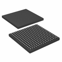
AD6636CBCZ Analog Devices Inc, AD6636CBCZ Datasheet - Page 41

AD6636CBCZ
Manufacturer Part Number
AD6636CBCZ
Description
IC DIGITAL DWNCONV 4CH 256CSPBGA
Manufacturer
Analog Devices Inc
Series
AD6636r
Datasheet
1.AD6636BCPCB.pdf
(80 pages)
Specifications of AD6636CBCZ
Rf Type
Cellular, CDMA2000, EDGE, GPRS, GSM
Number Of Mixers
1
Secondary Attributes
Down Converter
Current - Supply
450mA
Voltage - Supply
3 V ~ 3.6 V
Package / Case
256-CSPBGA
Brief Features
4/6 Independent Wideband Processing Channel, Quadrature Correction & DC Correction For Complex Input
Supply Voltage Range
1.7V To 1.9V
Operating Temperature Range
-40°C To +85°C
Ic Function
Digital Down Converter (DDC)
Rohs Compliant
Yes
Pin Count
256
Screening Level
Industrial
Package Type
CSPBGA
Lead Free Status / RoHS Status
Lead free / RoHS Compliant
Frequency
-
Gain
-
Noise Figure
-
Lead Free Status / Rohs Status
Compliant
Available stocks
Company
Part Number
Manufacturer
Quantity
Price
Company:
Part Number:
AD6636CBCZ
Manufacturer:
ADI
Quantity:
240
Three sources of error can be introduced by the AGC function:
underflow, overflow, and modulation. Underflow is caused by
truncation of bits below the output range. Overflow is caused by
clipping errors when the output signal exceeds the output range.
Modulation error occurs when the output gain varies while
receiving data.
The desired signal level should be set based on the probability
density function of the signal, so that the errors due to under-
flow and overflow are balanced. The gain and damping values
of the loop filter should be set so that the AGC is fast enough to
track long-term amplitude variations of the signal that may
cause excessive underflow or overflow but slow enough to avoid
excessive loss of amplitude information due to the modulation
of the signal.
AGC Loop
The AGC loop is implemented using a log-linear architecture. It
contains four basic operations: power calculation, error calcula-
tion, loop filtering, and gain multiplication.
The AGC can be configured to operate in either desired signal
level mode or desired clipping level mode. The mode is set by
the AGC clipping error bit of the AGC control register. The
AGC adjusts the gain of the incoming data according to how far
it is from a given desired signal level or desired clipping level,
depending on the selected mode of operation.
Two datapaths to the AGC loop are provided: one before the
clipping circuitry and one after the clipping circuitry, as shown
in Figure 39. For the desired signal level mode, only the I/Q
path from before the clipping is used. For the desired clipping
level mode, the difference of the I/Q signals from before and
after the clipping circuitry is used.
Q
I
1 – (1 + P) × z
BITS
22
POWER OF 2
K × z
2×
–1
–1
GAIN MULTIPLIER
+ P × z
–2
E ERROR
THRESHOLD
Figure 39. Block Diagram of the AGC
Rev. A | Page 41 of 80
K1 GAIN
K2 GAIN
P POLE
AVERAGE 1 – 16384 SAMPLES
DECIMATE 1 – 4096 SAMPLES
MEAN SQUARE (I
ERROR
SQUARE ROOT
log
Desired Signal Level Mode
In this mode of operation, the AGC strives to maintain the
output signal at a programmable set level. The desired signal
level mode is selected by writing Logic 0 into the AGC mode bit
of the AGC control register. The loop finds the square (or
power) of the incoming complex data signal by squaring I and
Q and adding them.
The AGC loop has an average and decimate block. This average
and decimate operation takes place on power samples and
before the square root operation. This block can be pro-
grammed to average from 1 to 16,384 power samples, and the
decimate section can be programmed to update the AGC once
every 1 to 4,096 samples. The limitation on the averaging
operation is that the number of averaged power samples should
be a multiple of the decimation value (1×, 2×, 3×, or 4×).
The averaging and decimation effectively means that the AGC
can operate over averaged power of 1 to 16,384 output samples.
Updating the AGC once every 1 to 4,096 samples and operating
on average power facilitates the implementation of the loop
filter with slow time constants, where the AGC error converges
slowly and makes infrequent gain adjustments. It is also useful
when the user wants to keep the gain scaling constant over a
frame of data or a stream of symbols.
Due to the limitation that the number of average samples must
be a multiple of the decimation value, only the multiple
numbers 1, 2, 3, or 4 are programmed. This is set using the
AGC average samples word in the AGC average sample register.
These averaged samples are then decimated with decimation
ratios programmable from 1 to 4,096. This decimation ratio is
defined in the 12-bit AGC update decimation register.
2
CLIP
CLIP
(x)
R DESIRED
2
+ Q
PROGRAMMABLE
2
)
BIT WIDTH
USED ONLY FOR
DESIRED CLIPPING
LEVEL MODE
Q
I
AD6636


