IP-POSPHY4 Altera, IP-POSPHY4 Datasheet
IP-POSPHY4
Specifications of IP-POSPHY4


Related parts for IP-POSPHY4


IP-POSPHY4 Summary of contents
Page 1
... POS-PHY Level 4 MegaCore Function User Guide 101 Innovation Drive San Jose, CA 95134 www.altera.com UG-IPPOSPHY4-10.1 POS-PHY Level 4 MegaCore Function Document last updated for Altera Complete Design Suite version: User Guide 10.1 December 2010 Document publication date: Subscribe ...
Page 2
... Altera warrants performance of its semiconductor products to current specifications in accordance with Altera's standard warranty, but reserves the right to make changes to any products and services at any time without notice. Altera assumes no responsibility or liability arising out of the application or use of any information, product, or service described herein except as expressly agreed to in writing by Altera. Altera customers are advised to obtain the latest version of device specifications before relying on any published information and before placing orders for products or services ...
Page 3
... Chapter 1. About This MegaCore Function Release Information . . . . . . . . . . . . . . . . . . . . . . . . . . . . . . . . . . . . . . . . . . . . . . . . . . . . . . . . . . . . . . . . . . . . . 1–1 Device Family Support . . . . . . . . . . . . . . . . . . . . . . . . . . . . . . . . . . . . . . . . . . . . . . . . . . . . . . . . . . . . . . . . . . . 1–1 Features . . . . . . . . . . . . . . . . . . . . . . . . . . . . . . . . . . . . . . . . . . . . . . . . . . . . . . . . . . . . . . . . . . . . . . . . . . . . . . . . 1–2 General Description . . . . . . . . . . . . . . . . . . . . . . . . . . . . . . . . . . . . . . . . . . . . . . . . . . . . . . . . . . . . . . . . . . . . . 1–3 Interfaces & Protocols . . . . . . . . . . . . . . . . . . . . . . . . . . . . . . . . . . . . . . . . . . . . . . . . . . . . . . . . . . . . . . . . . 1–4 SPI-4.2 Interface . . . . . . . . . . . . . . . . . . . . . . . . . . . . . . . . . . . . . . . . . . . . . . . . . . . . . . . . . . . . . . . . . . . . 1–4 Atlantic Interface . . . . . . . . . . . . . . . . . . . . . . . . . . . . . . . . . . . . . . . . . . . . . . . . . . . . . . . . . . . . . . . . . . . 1–5 Avalon-MM Interface . . . . . . . . . . . . . . . . . . . . . . . . . . . . . . . . . . . . . . . . . . . . . . . . . . . . . . . . . . . . . . . 1–5 MegaCore Verification . . . . . . . . . . . . . . . . . . . . . . . . . . . . . . . . . . . . . . . . . . . . . . . . . . . . . . . . . . . . . . . . . . . 1–5 Performance and Resource Utilization . . . . . . . . . . . . . . . . . . . . . . . . . . . . . . . . . . . . . . . . . . . . . . . . . . . . . . 1–6 Installation and Licensing . . . . . . . . . . . . . . . . . . . . . . . . . . . . . . . . . . . . . . . . . . . . . . . . . . . . . . . . . . . . . . . . 1–9 OpenCore Plus Evaluation . . . . . . . . . . . . . . . . . . . . . . . . . . . . . . . . . . . . . . . . . . . . . . . . . . . . . . . . . . . . 1– ...
Page 4
... Individual Buffers . . . . . . . . . . . . . . . . . . . . . . . . . . . . . . . . . . . . . . . . . . . . . . . . . . . . . . . . . . . . . . . . . . 5–3 Individual Buffers Transmit Scheduler (tx_sched 5–3 Data Processor (tx_data_proc 5–4 Atlantic Conversion . . . . . . . . . . . . . . . . . . . . . . . . . . . . . . . . . . . . . . . . . . . . . . . . . . . . . . . . . . . . . . . . . 5–4 Control Word Insertion, DIP-4, and Training Pattern Insertion . . . . . . . . . . . . . . . . . . . . . . . . . . . . 5–4 Parallel to Serial Converter (tx_data_phy_altlvds 5–5 Status Processor . . . . . . . . . . . . . . . . . . . . . . . . . . . . . . . . . . . . . . . . . . . . . . . . . . . . . . . . . . . . . . . . . . . . . . 5–6 Status Channel Interpretation Modes . . . . . . . . . . . . . . . . . . . . . . . . . . . . . . . . . . . . . . . . . . . . . . . . . . 5–7 Status Bypass Port . . . . . . . . . . . . . . . . . . . . . . . . . . . . . . . . . . . . . . . . . . . . . . . . . . . . . . . . . . . . . . . . . . 5–7 Clock Structure . . . . . . . . . . . . . . . . . . . . . . . . . . . . . . . . . . . . . . . . . . . . . . . . . . . . . . . . . . . . . . . . . . . . . . . . . 5– ...
Page 5
... Contents Chapter 6. Testbench Receiver Testbench Description . . . . . . . . . . . . . . . . . . . . . . . . . . . . . . . . . . . . . . . . . . . . . . . . . . . . . . . . . . . 6–1 Receiver Testbench Examples . . . . . . . . . . . . . . . . . . . . . . . . . . . . . . . . . . . . . . . . . . . . . . . . . . . . . . . . . . . . . 6–3 Transmitter Testbench Description . . . . . . . . . . . . . . . . . . . . . . . . . . . . . . . . . . . . . . . . . . . . . . . . . . . . . . . . 6–6 Appendix A. Start-Up Sequence Troubleshooting . . . . . . . . . . . . . . . . . . . . . . . . . . . . . . . . . . . . . . . . . . . . . . . . . . . . . . . . . . . . . . . . . . . . . . . . A–3 Issues and Tips—Transmitter . . . . . . . . . . . . . . . . . . . . . . . . . . . . . . . . . . . . . . . . . . . . . . . . . . . . . . . . . . A–3 Issues and Tips—Receiver . . . . . . . . . . . . . . . . . . . . . . . . . . . . . . . . . . . . . . . . . . . . . . . . . . . . . . . . . . . . . A–3 Issues and Tips—Miscellaneous . . . . . . . . . . . . . . . . . . . . . . . . . . . . . . . . . . . . . . . . . . . . . . . . . . . . . . . . A–5 Appendix B. Sharing PLLs for Multicore Designs Appendix C ...
Page 6
... POS-PHY Level 4 MegaCore Function User Guide Contents December 2010 Altera Corporation ...
Page 7
... HardCopy device family. The core meets all functional and timing requirements for the device family and can be used in production designs. ® POS-PHY Level 4 Description 10.1 December 2010 IP-POSPHY4 0088 6AF7 MegaCore IP Library Release Notes ® II software compiles the MegaCore IP Library Release Notes HardCopy Device Families ...
Page 8
... Table 1–3 shows the level of support offered by the POS-PHY Level 4 MegaCore function to each Altera device family. Table 1–3. Device Family Support Device Family ® Arria GX Arria II GX Arria II GZ ® Cyclone Cyclone II Cyclone III Cyclone III LS Cyclone IV HardCopy II HardCopy III HardCopy IV E ® ...
Page 9
... Status framing hysteresis (good and bad thresholds) ■ DIP-4 hysteresis (good and bad thresholds) ■ ■ IP functional simulation models for use in Altera-supported VHDL and Verilog HDL simulators ■ I-Tested certification General Description The packet over SONET/SDH physical layer (POS-PHY) Level 4 interface, first developed by the SATURN Internetworking Forum (OIF) as the System Packet Interface Level 4— ...
Page 10
... Avalon You can use multiple Atlantic interfaces, but the SPI-4.2 interface only supports a single transmitter and a single receiver. SPI-4.2 Interface The SPI-4.2 interface is an external interface protocol developed by the Optical Internetworking Forum (OIF). The SPI-4.2 interface features a high-speed data portion and a FIFO buffer status portion ...
Page 11
... For further information on this interface, refer to the Specification. Avalon-MM Interface The Altera Avalon-MM interface is a simple bus architecture that connects on-chip processors (or external processor interfaces) and peripherals. The Avalon-MM interface specifies the port connections between master and slave components, and specifies the timing by which these components communicate. ...
Page 12
... Chapter 1: About This MegaCore Function Performance and Resource Utilization Memory Blocks clk (1) f (MHz) M9K MAX 10 179 10 175 11 162 9 140 10 146 Memory Blocks clk (1) f (MHz) MAX M9K 10 193 17 266 23 138 10 172 17 275 23 158 11 203 14 260 8 151 December 2010 Altera Corporation ...
Page 13
... Transmitter 128 10 Table 1–7. Performance—Individual Buffers Mode—Cyclone III Device (Part Parameters Data Path Width Data Flow Direction (bits) 32 Receiver 32 32 December 2010 Altera Corporation Logic ALUTs Number of Registers Ports 4 875 850 4 944 1,326 4 1,177 1,456 10 901 939 10 1,042 ...
Page 14
... MAX 36 139 37 253 71 149 84 126 85 230 10 130 10 193 18 146 34 134 34 179 66 125 82 128 82 156 clk Memory f (MHz) MAX Blocks EP4SGX70 EP4SGX230 (M9K) DF29C3 DF29C3ES 21 182 159 40 270 268 78 165 149 45 140 144 88 255 254 December 2010 Altera Corporation ...
Page 15
... Installation and Licensing The POS-PHY Level 4 MegaCore function is part of the MegaCore IP Library, which is distributed with the Quartus II software and downloadable from the Altera website (www.altera.com). f For system requirements and installation instructions, refer to Installation and Figure 1–4 shows the directory structure after you install the POS-PHY Level 4 MegaCore function, where < ...
Page 16
... OpenCore Plus Evaluation With Altera’s free OpenCore Plus evaluation feature, you can perform the following actions: Simulate the behavior of a megafunction (Altera MegaCore function or AMPP ■ megafunction) within your system Verify the functionality of your design, as well as evaluate its size and speed ■ ...
Page 17
... The POS-PHY Level 4 MegaCore function is in the Communications > POS-PHY directory. 3. Click Step 1: Parameterize in IP Toolbench. 4. Determine your design’s constraints and performance requirements and then parameterize the POS-PHY Level 4 MegaCore function in IP Toolbench. 1 Not all parameters are supported by, or are relevant for, every MegaCore function variation. ...
Page 18
... A Tcl script that regenerates the IP functional simulation model, in both Verilog HDL (.vo) and VHDL (.vho) formats. A Tcl script that automates the process of running the testbench with the IP functional simulation model. An OpenCore Plus file, for time limited or tethered hardware evaluation. ...
Page 19
... After you review the generation report, click Exit to close IP Toolbench and click Yes on the Quartus II IP Files message. 1 The Quartus II IP File (.qip file generated by the MegaWizard interface or SOPC Builder that contains information about a generated MegaCore function ...
Page 20
... Start the ModelSim simulator the simulator, change the working directory to the location of the <variation_name>_run_modelsim.tcl file run the script type the following command at the simulator command prompt: source <variation_name>_run_modelsim.tcl Use the Testbench with NativeLink To use the testbench with third-party IP functional simulation models using NativeLink, follow these steps: 1 ...
Page 21
... When you have entered the required information for your new testbench, click OK in the New Test Bench Settings dialog box. 9. Click OK in the Test Benches dialog box and then click OK in the Settings dialog box. December 2010 Altera Corporation (refer also to Figure 2–2 on page Parameter < ...
Page 22
... Compile the Design and Program a Device You can use the Quartus II software to compile your design. Refer to Quartus II Help for instructions on compiling your design. After you have compiled your design, program your targeted Altera device and verify your design in hardware. POS-PHY Level 4 MegaCore Function User Guide ...
Page 23
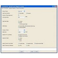
... You customize the POS-PHY Level 4 MegaCore using IP Toolbench launched from the MegaWizard ® Quartus II software. This chapter describes the parameters and how they affect the behavior of the MegaCore function. Each section corresponds to a tab when you click Parameterize in IP Toolbench. Basic Parameters Figure 3– ...
Page 24
... POS-PHY Level 4 MegaCore Function User Guide Device Family ™ “DPA Channel Aligner 4–3. Chapter 3: Parameter Settings Basic Parameters LVDS Rate (Mbps) 840 1,000 622 622 622 622 1,040 840 1,040 1,040 1,250 1,250 1,250 1,000 interface transmitter where December 2010 Altera Corporation ...
Page 25
... IP Toolbench uses this parameter to instantiate and configure the ALTLVDS megafunction that includes the fast PLL. For example, to configure a transmitter with a data rate of 700 Mbps on the tdat line, enter 700 in the LVDS Data Rate field of IP Toolbench. This rate corresponds to a 350 MHz DDR clock on tdclk. ...
Page 26
... The POS-PHY Level 4 MegaCore function supports the following sizes (per buffer): 512 bytes ■ ■ 1,024 bytes POS-PHY Level 4 MegaCore Function User Guide 5–3. 4–7. Chapter 3: Parameter Settings Basic Parameters “Individual “Individual December 2010 Altera Corporation ...
Page 27
... With a multiple Atlantic FIFO buffer clocks, the Atlantic FIFO buffers are instantiated as multiple clock domain buffers. Each buffer has two independently operated clock inputs, thus each Atlantic interface has a separate clock input. Multiple Atlantic FIFO buffer clocks consume more logic resources. ...
Page 28
... Atlantic error checking is often desirable for receivers, but less applicable for transmitters because the incoming user-Atlantic data may be presumed correct. POS-PHY Level 4 MegaCore Function User Guide shows the Optional Features tab. Chapter 3: Parameter Settings Optional Features December 2010 Altera Corporation ...
Page 29
... In the Pessimistic mode, the latest status information is captured and is stored inside the status processor block until a DIP-2 status is received. If the DIP-2 is valid, the buffered status is passed on to the scheduler or user logic. If the DIP-2 is invalid, the scheduler and user logic do not receive an update, and the next incoming status overwrites the errored buffered status ...
Page 30
... MSOP/EOP errors. If you turn on Ignore LVDS DPA locked after training, a loss of dpa_lvds_locked does not trigger stop and framing, and data continues to process normally. You must monitor the DIP4 error signal to assess if the data is correct or not and trigger a retrain or not. 1 ...
Page 31
... Optimistic mode—the receiver MegaCore function marks the preceding and ■ succeeding burst as errored. If these bursts are payload (that is DIP-4 occurs followed by IDLEs), then only the preceding control word payload is marked as errored. Bursts going into the Atlantic FIFO buffer are marked with the Atlantic error signal burst is not an EOP the user logic to detect it. Pessimistic mode— ...
Page 32
... When you select 2 FIFO RAM blocks, the timing performance of the MegaCore function may decrease (because the memory rdata bus is unregistered, as opposed to registered for 4 FIFO RAM blocks). Altera recommends that you do full compilations for both configurations before deciding which one to choose. 1 Use 2 FIFO RAM block only if it gives an improvement in memory utilization and if your timing requirements are still met ...
Page 33
... M4K 8,192 24 M4K Note to Table 3–5: (1) Stratix II device, receive (Rx), shared buffer, data path width 32, parity enabled. December 2010 Altera Corporation Figure 3–3 shows the comparison of FIFO RAM blocks. 4 FIFO RAM Blocks FIFO Block 0 (size = fifo_size/4) FIFO Block 1 (size = fifo_size/4) Write Side ...
Page 34
... MegaCore function. These input pins allow each parameter to be connected to a user-implemented register, and controlled at run-time. Select Fixed Value, to enter values for the protocol parameters on this tab. IP Toolbench then fixes these values in the MegaCore function, making the parameters static and the input pins unavailable. Calendar Options ...
Page 35
... The calendar length value cannot be greater than the number of ports (except when you turn on Asymmetrical Port Support). The Calendar multiplier determines the number of times the calendar sequence is repeated before the DIP-2 parity and framing is inserted. Choose a value from 1 to 256. If the Asymmetric Port Support is turned on, the calendar multiplier value is programmed via the Avalon-MM interface ...
Page 36
... The burst unit size multiplier does not limit the maximum burst length, and does not force control word insertion. Instead, use the Burst limit parameter. When the data path width is equal to 128 bits and the lite transmitter feature is turned off, the unit size is 32 bytes 1,024 bytes in 32-byte granularity. The MaxBurst1 parameter allows you to select the maximum number of credits— ...
Page 37
... The stat_ts_sync signal is asserted high when a good_level number of consecutive status frames are received without frame or DIP-2 errors. The stat_ts_sync signal is deasserted when a bad_level number of DIP-2 errors or frame errors have been received since the last error-free frame. The FIFO buffer threshold high (FTH) for transmitter variations controls when the aN_atxdav signal is asserted and deasserted for the write side of the FIFO buffer ...
Page 38
... These thresholds are defined in terms of bytes, with a valid range from zero to buffer size must be lower than or equal to AF. Figure 3–5 illustrates the relationship between the AE and AF thresholds and the MaxBurst1 and MaxBurst2 values. Figure 3–5. FIFO Buffer Thresholds (Empty) Notes to Figure ...
Page 39
... If the bad counter reaches the bad_level threshold, the stat_rd_dip4_oos flag is asserted. A bad_level invalid. 1 The receiver may need to receive more control word DIP-4 errors than the DIP-4 bad threshold parameter set in the wizard, for stat_rd_dip4_oos to go high. f For more information, refer to Service Indication” ...
Page 40
... POS-PHY Level 4 MegaCore Function User Guide Chapter 3: Parameter Settings Protocol Parameters December 2010 Altera Corporation ...
Page 41
... Atlantic interface. Features ■ Accepts packets from a SPI-4.2 transmitter ■ Processes control words Detects diagonal interleaved parity (DIP-4) errors ■ Detects SPI-4.2 protocol errors ■ Performs start-of-packet (SOP) alignment and Atlantic conversion ■ Buffers packets on a per-port or per-interface basis ■ ...
Page 42
... DPA Channel Data Aligner Processor Status FSM Status Status Hold Register Status Calculator rav_clk ® III, Stratix II, Stratix GX, and Stratix devices Chapter 4: Functional Description—Receiver Block Description Atlantic Interface 0 Atlantic Buffer 0 Atlantic Interface N Atlantic Buffer N rxsys_clk December 2010 Altera Corporation ...
Page 43
... Chapter 4: Functional Description—Receiver Block Description f For more information on the ALTLVDS_RX and ALTDDIO_IN megafunctions, refer to ® Quartus II Help, to the Guide the DPA Channel Aligner (rx_data_phy_dpa) In the Stratix III, Stratix II, and Stratix GX device families, the ALTLVDS_RX megafunctions support an optional DPA feature that can compensate for trace length mismatches and variations due to process, voltage, and temperature (PVT) ...
Page 44
... If the traffic on the SPI-4.2 interface is very sparse, periodic training patterns may be required. To compensate for large amounts of static channel-to-channel skew, the POS-PHY Level 4 MegaCore function channel aligner state machine uses the bit slip feature (the channel align or data realignment) of the ALTLVDS_RX megafunction. The POS-PHY Level 4 MegaCore function automatically configures and includes the ALTLVDS_RX megafunction ...
Page 45
... Serializer The 8:4 serializer block supports an overall deserialization factor of 4 for 64-bit Stratix GX variations only. It consists of a PLL and a 2:1 multiplexer for each channel. f For more information on using dynamic phase alignment, refer to and Dynamic Phase Data Processor (rx_data_proc) The data processor consists of three sub-blocks ...
Page 46
... MegaCore function data path width. f For a description of the relationship between rdint_clk and rxsys_clk, refer to “Clock Structure” on page SOP Alignment & Atlantic Conversion This block moves the SOP for each packet to the first-byte position on the Atlantic interface, and aligns the data to ensure that valid data is contiguous (no IDLEs) before sending it to the Atlantic buffer ...
Page 47
... Chapter 4: Functional Description—Receiver Block Description The shared buffer and the logic support up to 256 ports. If Atlantic error checking is enabled, 256 ports are still supported by the MegaCore function, but the logic for error checking uses only the minimum amount of logic required to support the number of ports chosen as a parameter ...
Page 48
... Memory-Mapped (Avalon-MM) interface is set, the finite state machine outputs ‘11’ continuously and the stat_ry_disabled signal is asserted. Framing, calendar select word, and DIP are generated locally, but the actual status for each calendar slot is provided on request by the status register (rx_stat_proc_reg) block, and either the status calculator (rx_stat_calc) or status hold (rx_stat_hold) blocks ...
Page 49
... Chapter 4: Functional Description—Receiver Block Description 1 Due to the round trip latency of the status channel, especially at high calendar lengths, the hysteresis between the AE and AF values (in addition to the possibility of the override capabilities listed above) may be such that a transition from starving to satisfied (and vice versa) can occur. In the event that a transmitting device does not ...
Page 50
... Multiple Clock Mode If you select the multiple clock domain mode, the rxsys_clk clock clocks the protocol logic of the MegaCore function, and the write side of the Atlantic FIFO buffers. In multiple clock domain mode, an input clock is instantiated for each Atlantic FIFO buffer in the MegaCore function, which is used for the read side of the buffers ...
Page 51
... PLL where it generates rdint_clk (×1). The PLL is required to provide 90° phase shift, so the ALTDDIO_IN megafunction samples in the centre of the data eye. A typical system may have a rdint_clk of 100 MHz, of which December 2010 Altera Corporation shows the multiple clock domain clocking structure for the rdint_clk DPA/ Channel ...
Page 52
... Data ALTDDIO_IN Processor EPLL (Note 4) Status ALTDDIO_OUT Processor 2 Worst Case Frequency Requirement 1.0 × rdint_clk 1.25 × rdint_clk 1.6 × rdint_clk rxsys_clk. Chapter 4: Functional Description—Receiver Reset Structure a0_arxclk Atlantic Atlantic Buffer 0 Interface 0 aN_arxclk (Note 2, 3) Atlantic Atlantic Interface N Buffer N rxsys_clk ...
Page 53
... Chapter 4: Functional Description—Receiver Error Flagging and Handling Asserting reset deletes all data in the buffers, and resets all state bits. In addition to the reset, asynchronous reset and locked signals are provided for the internal PLL, if present. The PLL should be reset and stable along with all other clocks before the reset is released ...
Page 54
... Malformed data bus during a data or control word. ■ Missing IDLE before training pattern begins. (The IDLE ■ can be an EOP). 8N boundary error A burst that is neither a multiple of 16 bytes, nor an EOP. (8N_ERR) POS-PHY Level 4 MegaCore Function User Guide Chapter 4: Functional Description—Receiver (Note 1), ...
Page 55
... Single DIP-4 error current control word and preceding data. A DIP-4 error occurs when the DIP-4 calculated over the rdat line does not match the DIP-4 value in the control word. December 2010 Altera Corporation ...
Page 56
... Table 4–3. SPI-4.2 Protocol Error Handling (Part Error Data bus out of alignment (consecutive DIP-4 errors over a Burst of DIP-4 errors programmable threshold) A packet address error (err_ry_paddr) occurs when a Packet address error packet is received with an out-of-range port address. Notes to Table 4–3: (1) More than one error of the same type may occur per internal clock. In such a case, the error is only asserted once. ...
Page 57
... In cases where the terminating control word contains an EOP, the associated aN_arxmty value is not rounded down to the nearest even value. Pessimistic Mode In the event of a DIP-4 error, all open packets are marked. All subsequent data for each port is marked until a new SOP for that port is received. 1 Because of the logic required to track open packets per ports, this feature uses a large amount of logic for systems with many ports ...
Page 58
... If the receiver is in service and the bad threshold is set the receiver goes out of service as soon as a single DIP-4 error is detected. If the receiver is out of service and there are no DIP-4 errors in the current rdint_clk clock cycle, the good counter is incremented. If the good counter reaches the good_level threshold, the receiver goes in service and asserts ...
Page 59
... Bus (Four-Lane) Bad DIP-4 Counter Notes to Figure (1) Receiving a good and a bad DIP-4 in the same parallel cycle resets the counter (does not increment it), so that OOS does not trigger. f For further information on the DIP-4, refer to the System Packet Interface Level 4 (SPI-4) Phase 2 Revision 1: OC-192 System Interface for Physical and Link Layer Devices, available at www ...
Page 60
... If an EOP is forced, the aN_atxerr output signal ■ is asserted. Generally this signal can be ignored, unless the aN_atxeop signal is also asserted. Chapter 4: Functional Description—Receiver Error Flagging and Handling Response “Missing SOP” on page 4–22. December 2010 Altera Corporation ...
Page 61
... Chapter 4: Functional Description—Receiver Error Flagging and Handling Table 4–4. Atlantic Error Handling (Part Error ■ ■ Atlantic buffer overflow Atlantic buffer underflow — The Atlantic FIFO buffer error checker block checks for missing SOP and EOP markers, for each port. If these markers are found to be missing, their respective err_ry_msopN and err_ry_meopN signals are asserted (high). These signals remain high for one rxsys_clk cycle. These error conditions do not correlate directly— ...
Page 62
... Figure 4–10. Missing SOP Output Timing Diagram aN_arxsop aN_arx eop err_ry_msopN POS-PHY Level 4 MegaCore Function User Guide aN_arxtclk aN_arxena aN_arxerr Chapter 4: Functional Description—Receiver Error Flagging and Handling Figure 4–10). Missing SOP December 2010 Altera Corporation ...
Page 63
... Chapter 4: Functional Description—Receiver Error Flagging and Handling Missing EOP Figure 4–11 and err_ry_meop signal is asserted, an EOP is forced, the err signal is asserted, and data is ignored for that port until an EOP is received. Figure 4–11. Missing EOP Input Timing Diagram aN_atxtclk aN_atxena aN_atxsop ...
Page 64
... Locked signal directly from fast PLL in ALTVDS for full rate Asynchronous variations, or enhanced PLL in quarter-rate variations. Asynchronous reset signal directly to fast PLL in ALTVDS for Asynchronous full rate variations, or enhanced PLL in quarter-rate variations. Chapter 4: Functional Description—Receiver Signals Description Description “Reset Structure” on December 2010 Altera Corporation ...
Page 65
... Chapter 4: Functional Description—Receiver Signals Table 4–7. Atlantic Receive Interface (Slave Source) Signal Direction Clock Domain Input aN_arxclk Output aN_arxdav Input aN_arxena Output aN_arxdat[n:0] Output aN_arxval aN_arxclk Output aN_arxsop Output aN_arxeop Output aN_arxmty[n:0] Output aN_arxerr Output aN_arxadr[7:0] Note to Table 4–7: ( equal to the number of ports for the individual buffers mode equal to zero for the shared buffer with embedded addressing mode. ...
Page 66
... Status for port indicated by ctl_ry_extstat_adr. Input This value is ignored if ctl_ry_fifostatoverride is deasserted. Input - Controls the edge of rsclk on which transitions of Static rstat occur positive edge negative edge). rsclk constant Only change at reset. Chapter 4: Functional Description—Receiver Signals Description Description December 2010 Altera Corporation ...
Page 67
... You can use ctl_ry_rsfrm to indicate that the receiver requires retraining. If you assert ctl_ry_dip2err_ins while it is calculating the DIP2, it inverts it. It does not invert the statuses on the way and does not wait for the end of the calendar to do the inversion. Also, if the error is set for ...
Page 68
... This port is absent if asymmetric port support is turned off. Avalon-MM address. This port is absent if asymmetric Input port support is turned off. Avalon-MM chip select. This port is absent if Input asymmetric port support is turned off. Avalon-MM write enable. This port is absent if Input asymmetric port support is turned off ...
Page 69
... Number of consecutive DIP-4 errors to set stat_rd_dip4_oos. Only change at reset. Receiver’s out-of-service flag. When asserted, the MegaCore function is still passing data, but is receiving DIP-4 errors above a threshold. Each clock cycle asserted indicates that one or more (depending on the data path width parameter) calculated DIP-4 values did not match the received DIP-4 values ...
Page 70
... If write, CALMEM_ADR is applied to the write address of RAM and CALMEM_DAT1 is applied to the write data. Read write indirect data If read, CALMEM_ADR is applied to read address of RAM, and resulting read data is captured in CALMEM_DAT1. Reserved Reserved. Chapter 4: Functional Description—Receiver Avalon-MM Interface Register Map Description December 2010 Altera Corporation ...
Page 71
... Chapter 4: Functional Description—Receiver Latency Information Latency Information The receiver MegaCore functions involve two kinds of latency: data latency and status transmit latency. Data latency is defined as the latency from the SPI-4.2 LVDS receive pins to the internal Atlantic interface that is writing into the buffer(s). For the shared buffer with embedded addressing mode, it does not include the time the data spends in the buffer ...
Page 72
... The values in ■ For 64- and 128-bit data path width variations, the values assume that the clock- crossing buffer is empty. Additional latency should be added if multiple continue traffic is expected. ■ The DPA adds 32 bytes for a 128-bit data path, and 16 bytes for a 64-bit data path. ...
Page 73
... The dotted lines illustrate the clock domain separations. (2) These blocks and signals are only present when the individual buffers mode is selected. December 2010 Altera Corporation 5. Functional Description—Transmitter ® function consists of the main SPI-4.2 processing ™ interface to the SPI-4.2 interface. ...
Page 74
... The Atlantic FIFO buffers provide the following features: ■ Slave-sink Atlantic interface on the user side ■ Configurable buffer size ■ Multiple clock domain support ■ Overflow error indication and FIFO buffer empty indication ■ Atlantic interface error checking Missing or spurious start-of-packet (SOP)/end-of-packet (EOP) detection and ■ ...
Page 75
... Chapter 5: Functional Description—Transmitter Block Description When the ignore backpressure feature is turned on, the transmitter sends packets whenever possible regardless of the incoming status channel. This mode assumes that external logic is properly controlling the scheduling of ports, managing credits (topping up to MaxBurst1 and MaxBurst2 as appropriate), and performing any other related functions ...
Page 76
... Control Word Insertion, DIP-4, and Training Pattern Insertion This block inserts control words into the data path, and performs DIP-4 calculation and insertion. An EOP-abort condition can be generated on the SPI-4.2 interface by asserting aN_atxerr with a valid aN_atxeop on the Atlantic interface ...
Page 77
... The lite transmitter mode is chosen by turning on Lite Transmitter in IP Toolbench. The lite transmitter uses a smaller, less efficient version of the Atlantic converter that allows packets to be padded with IDLE characters to a multiple of 16 bytes for 128-bit variations bytes for 64-bit variations. Although turning on Lite Transmitter lowers the effective bandwidth rate on the SPI-4 ...
Page 78
... Status Processor The transmitter MegaCore function monitors and decodes the tstat status channel from the receiver. It handles framing, checking for DIP-2 errors, and extracting status. The status is provided to the transmit scheduler if present, and is always available to the user logic. The clock edge on which the transmitter samples the status channel is programmable ...
Page 79
... Optimistic Mode The status information is provided to the user and transmit scheduler as soon as it can pass through the clock-crossing FIFO buffers, before the DIP-2 cycle is even received. DIP-2 errors are flagged, but have no effect on the status provided to the user the scheduler either mode, the stat_ts_dip2state signal indicates when a DIP-2 has been received at the finite state machine ...
Page 80
... Clock Structure With the Atlantic FIFO clock mode parameter in IP Toolbench, you can parameterize the transmitter in one of the following two clocking structures: ■ Single clock domain ■ Multiple clock domain All data path width variations of the MegaCore function use a common clocking structure ...
Page 81
... Clock Domain The trefclk clock is the input to the MegaCore function. The tdint_clk clock is an output wire, and is the output of a fast PLL. The trefclk can be generated from multiple possible Transmit MegaCore function sources, for various frequencies. For example, a SPI-4.2 bus rate of 800 Mbps requires a ...
Page 82
... SPI-4.2 mode variations. For 32-bit variations, the ALTLVDS_TX block is replaced by an ALTDDIO_OUT block and there is no LVDS PLL function that is clocked by trefclk. POS-PHY Level 4 MegaCore Function User Guide shows the multiple clock domain clocking structure for the tdint_clk altlvds Megafunction Data ...
Page 83
... Chapter 5: Functional Description—Transmitter Reset Structure 1 The SPI-4.2 tdclk is not a separate clock domain because it is not on an FPGA clock signal. Instead, alternating 1s and 0s are preloaded into the tdclk serializer. As tdclk is generated using the same PLL as the rest of the data, the clock and data are launched at the same time ...
Page 84
... A DIP-2 error occurs when the DIP-2 code locally calculated on the received status message does not match the DIP-2 received in the status message DIP-2 error occurs, the err_ts_dip2 signal is asserted at the end of the calendar sequence for a single clock cycle. A framing status error occurs for three regions: ■ ...
Page 85
... Error Flagging and Handling The stat_ts_sync signal is deasserted when a programmed bad_level number of calendar sequences with frame errors or DIP-2 errors is received without a good frame. When the stat_ts_sync signal is deasserted, the transmitter stops transmitting data on the nearest burst unit size boundary or at the next EOP, and starts sending the training patterns continuously (refer to Figure 5– ...
Page 86
... Table 5–2 summarizes the SPI-4.2 protocol errors. Table 5–2. SPI-4.2 Protocol Error Handling Error Single DIP-2 or frame error has been detected Assuming the bad_level input is greater than 1 (ctl_ts_sync_bad_theshold) Multiple consecutive DIP-2 or frame errors when sync is detected Causes the bad_level counter to go over ...
Page 87
... Chapter 5: Functional Description—Transmitter Error Flagging and Handling If a SOP is detected during an open packet, then err_aN_meopN is asserted. The packet is terminated with an EOP-Abort, and data is ignored for that port until an EOP is received MTY is non-zero when a missing EOP is not asserted, then err_aN_meopN is asserted. The packet is terminated with an EOP-Abort, and data is ignored for that port until a SOP is received ...
Page 88
... Table 5–3 through low signals are suffixed by _n. POS-PHY Level 4 MegaCore Function User Guide Figure 5–10 show missing EOP. Packet A aN_atxtclk Terminated Packet 5–24 list the transmitter MegaCore function I/O signals. The active Chapter 5: Functional Description—Transmitter Signals Packet Good Packet ...
Page 89
... Chapter 5: Functional Description—Transmitter Signals Table 5–3. SPI-4.2 Transmit Interface Signal Direction Output tdclk Output tctl Output tdat[15:0] Input tsclk Input tstat[1:0] Table 5–4. Global Signal Direction Input trefclk Output tdint_clk Input txsys_clk Input txreset_n Output txinfo_aot[12:0] Output stat_tx_pll_locked Input ctl_tx_pll_areset December 2010 Altera Corporation ...
Page 90
... Atlantic Error (one for each Atlantic interface). Translates to an EOP- Abort on the transmit data bus. Atlantic port address. Only present when you turn on turn on Shared Buffer with Embedded Addressing. Chapter 5: Functional Description—Transmitter Signals Description December 2010 Altera Corporation ...
Page 91
... Pessimistic behavior only passes status from the last Input - calendar multiplier in error free frames to the user tsclk Static reset and scheduler. Optimistic behavior has the least latency, passing all status to the user and scheduler before determining if the status frame is error free ...
Page 92
... Output ctl_ts_rsfrm is asserted. Deasserted when a potentially valid framing pattern is detected. A potentially valid framing word is ‘b11 followed by anything other than ‘b11. tsclk Indicates that the status state machine is in DIP-2 Output state. Indicates that the status state machine is in framing Output state. ...
Page 93
... Unexpected framing word was in the calendar ■ portion of the frame. Asserted synchronous to stat_ts_dip2state. Indicates the calculated DIP-2 did not match the DIP- Output 2 word in the status frame. Asserted synchronous to stat_ts_dip2state. Sets the expected length of the calendar in the status frame ...
Page 94
... Atlantic buffer(s), and sends idle control words or training patterns. This input is tied to one in the IP Toolbench top-level file, if you use the individual buffers mode. Only change at reset. Indicates if the MegaCore function is currently head- ...
Page 95
... Input transmitter parameters, the values may be limited to a minimum value. You can use IP Toolbench to determine the valid values (set Parameter Type to Fixed Value to determine the valid values, and then set back to Real Time Programmable). The units are in bytes. 5– ...
Page 96
... When ‘10’ or ‘11’, the scheduler switches when ■ ctl_td_burstlen data is sent EOP is sent. In the IP Toolbench top-level file, the upper bit is always ■ tied to zero, and the lower bit is tied depending on the value of the switch on end of packet feature. This port is absent if you turn on Shared Buffer with Embedded Addressing ...
Page 97
... Chapter 5: Functional Description—Transmitter Avalon-MM Interface Register Map 1 If the hitless bandwidth repositioning (HBWR) register is not enabled, the CALM1, CALLEN1, CALMEM_DAT registers become reserved. 1 Only change the CALM0, CALLEN0, CALMEM_DAT0 registers when the DISABLED register is equal when the CALSEL_ACT register is equal to 1. Only change the CALM1, CALLEN1, CALMEM_DAT1 registers when the DISABLED register is equal when the CALSEL_ACT register is equal to 0 ...
Page 98
... FIFO buffer is empty. Status receive latency is defined as the latency from the point at which the last cycle of a valid status message is received (the DIP-2 error code) to the point at which the user logic or the transmit scheduler can use the status information. It does not include the time spent waiting for a complete, error-free status message. Figure 5– ...
Page 99
... Chapter 5: Functional Description—Transmitter Latency Information Table 5–11 lists the latency numbers for transmitter variations. Table 5–11. Transmitter Latency MegaCore Function 128-bit shared buffer with embedded addressing 128-bit individual buffers 64-bit shared buffer with embedded addressing 64-bit individual buffers 32-bit shared buffer with embedded addressing ...
Page 100
... POS-PHY Level 4 MegaCore Function User Guide Chapter 5: Functional Description—Transmitter Latency Information December 2010 Altera Corporation ...
Page 101
... Synchronization of the MegaCore function with the SPI-4.2 training pattern ■ Data integrity from the SPI-4.2 interface through the MegaCore function variation to the Atlantic back-end interface Ability to send data to multiple ports ■ Verifies that the MegaCore function correctly drives backpressure on the SPI-4.2 ■ ...
Page 102
... The testbench consists of three basic modules: packet generation, user receiver variation, and a data analyzer. All testbench modules are in the <variation name>_tb.v file. The testbench also consists of multiple support modules for pin monitoring, clock generation, and reset generation (refer to generates SPI-4.2 packets. These packets are received by the receiver MegaCore function, which processes the packets and converts them to Atlantic interface format ...
Page 103
... December 2010 Altera Corporation Table 6–2 shows the format of each function. Description width is the number of clock cycles the training pattern takes; number is the number of training pattern sequences. number is the number of sequential idles port_number is the target port for the packet. err is set to zero; ...
Page 104
... This byte is then incremented for the rest of the packet. Sends a control word for one clock cycle. The DIP4 is auto word[15:0]is the control word to be inserted. calculated and When the dip4err bit is set, the DIP4 calculation is inserted into word inverted. [3:0]. The DIP4 calculation can be inverted. Chapter 6: Testbench ...
Page 105
... This error signal cannot be simulated with this version of the testbench. err_rd_abuf_oflw Using the pkt2 task, send in a packet with a missing EOP and a non 16-byte multiple length: err_rd_eightn spi_gen.pkt2(<port>,/*err*/3,65,<pkt_num>); December 2010 Altera Corporation General Description ...
Page 106
... Data integrity from the Atlantic back-end interface through the user’s configuration to the SPI-4.2 interface ■ Sends data from multiple ports to the SPI-4.2 interface ■ Verifies that the MegaCore function responds to backpressure on the SPI-4.2 interface (this test can be turned on and off) ...
Page 107
... The testbench consists of three basic modules: data generator, user transmitter variation, and packet analyzer. All testbench modules are in the <variation name>_tb.v file. The testbench also consists of multiple support modules for pin monitoring, clock generation, SPI-4.2 state machine tracking, and reset generation (refer to page 6– ...
Page 108
... Packet number (packet number begins at 'h01 and is incremented by one for each packet) XORed with the port number. The following bytes in the packet are incremented by one and XORed with the port number. Chapter 6: Testbench Transmitter Testbench Description December 2010 Altera Corporation ...
Page 109
... Chapter 6: Testbench Transmitter Testbench Description transmitter MegaCore function then resumes sending packets to those ports. When the FIFO buffer is satisfied, the status on the SPI-4.2 interface notifies the data generator module to stop sending data. There is a break in packet generation during which idles are sent. After the status returns to the hungry state, the packet generation resumes ...
Page 110
... POS-PHY Level 4 MegaCore Function User Guide Chapter 6: Testbench Transmitter Testbench Description December 2010 Altera Corporation ...
Page 111
... The startup sequence combines clock stabilization, reset, and configuration with the training and framing aspects of the SPI-4.2 protocol as shown in page A–1. Details of each event as they happen in the POS-PHY Level 4 MegaCore function are listed in implementations. December 2010 Altera Corporation ® POS-PHY Level 4 MegaCore function. Power up Assert all resets ...
Page 112
... A–2 1 For a 32-bit transmitter MegaCore function, no PLLs are used so the ctl_tx_pll_areset and stat_rx_pll_locked signals do not exist. Table A–1. Start-Up Sequence (Part Event Description Assert ctl_rx_pll_areset and rxreset_n. 1 Power Up The receiver MegaCore function sends framing pattern('b11) on rstat[1:0]. Release receiver PLL reset ...
Page 113
... The following tips may prove useful: For 128-bit receiver variations, ensure that the rxsys_clk to rdint_clk ratio is ■ set according to the receive clock setting in Ensure that the calendar length and calendar multiplier are set to the same ■ values in both devices. Verify timing requirements for the status channel. ...
Page 114
... The following tips may prove useful: For 128-bit receiver variations, ensure that the rxsys_clk to rdint_clk ratio is ■ set according to the receive clock setting in Ensure that the calendar length and calendar multiplier are set to the same ■ values in both devices. Verify timing requirements for the status channel ■ ...
Page 115
... Ensure that ctl_td_burstlen is less than the buffer size. ■ 8. Throughput is lower than expected. The following tips may prove useful: Understand quantization effects and choose transmitter mode (lite or non-lite), ■ data path width, and clock frequencies appropriate for your packet size and throughput needs ...
Page 116
... A–6 POS-PHY Level 4 MegaCore Function User Guide Appendix A: Start-Up Sequence Troubleshooting December 2010 Altera Corporation ...
Page 117
... Create a new Quartus II project, but call the project name and the top-level entity names different names. 2. Create your receiver core. 3. Create your transmitter core. December 2010 Altera Corporation B. Sharing PLLs for Multicore Designs Figure B–1 shows two PLLs, the Quartus II software optimizes the PLL ...
Page 118
... PLL. Use the following assignment to force the merging of the receiver and transmitter PLLs: set_instance_assignment -name FORCE_MERGE_PLL ON -from "<tx_pll>" -to "<rx_pll>" POS-PHY Level 4 MegaCore Function User Guide Appendix B: Sharing PLLs for Multicore Designs Figure B–2). December 2010 Altera Corporation ...
Page 119
... For example, consider a 128-bit MegaCore function with an LVDS data rate of 800 Mbps, using a single port, a calendar length of 1, and a calendar multiple of 1. For this example, rdint_clk = rsclk = 100 MHz. For a minimum packet size of 48 bytes, the required frequency for rxsys_clk from restriction (a) is (48 +2) / ...
Page 120
... MHz If you do not want to increase the rxsys_clk frequency, you can increase the status frame length. By setting the calendar multiple to 2, the required frequency from restriction (b) is Status frame length = 4 rxsys_clk frequency ≥ 102.5 × 5/4 = 128.125 MHz By changing the calendar multiple to 2, the required minimum rxsys_clk frequency is 131 ...
Page 121
... Trace lengths should match. Design for Testability High speed designs involving SPI-4.2 interfaces can be very complex. Altera recommends that you design the circuit board with debug testability in mind. This section describes recommended practices to follow while designing the board. ...
Page 122
... SPI-4.2 status interface signals: ■ rstat[1:0] ■ rsclk Other useful debug signals: ■ FPGA reset ■ stat_rd_dpa_locked ■ stat_rd_dpa_lvds_locked ■ ■ err_rd_dip4 ■ err_ry_msopN ■ err_ry_meopN ■ rdint_clk ■ aN_arxerr ■ aN_arxeop ■ aN_arxclk 1 In addition to these receiver signals, it may be useful to provide test points for similar debug and status signals from the adjacent device ...
Page 123
... Other Useful Debug Signals ■ FPGA reset ■ stat_ts_sync ■ err_ts_dip2 ■ err_ts_frm ■ trefclk 1 In addition to these transmitter signals, it may be useful to provide test points for similar debug and status signals from the adjacent device. Spare Pins The SignalProbe feature in the Quartus II software allows you to route signals inside the device to output pins so you can view the signals on an oscilloscope or logic analyzer, without recompiling the design ...
Page 124
... D–4 POS-PHY Level 4 MegaCore Function User Guide Appendix D: Board Design Design for Testability December 2010 Altera Corporation ...
Page 125
... The range of valid port numbers is zero to the number of ports - 1. You can set the maximum calendar length and number of ports for your variation of the POS-PHY Level 4 MegaCore function using IP Toolbench within the Quartus II software (refer to This approach requires that the receiver and transmitter MegaCore functions maintain identical tables that map each calendar slot number to a port address number ...
Page 126
... Write 0 to CALMEM_DAT0. ■ 5. Write a value into the CALM1 field, to set the calendar multiplier for calendar 1. 6. Write a 3 into the CALLEN1 field, to set the calendar length to 3 slots for calendar 1. 7. Map the calendar 1 slot numbers to the desired port numbers: a ...
Page 127
... Calendar tables may be updated whenever the status channel is inactive, or when the calendar to be modified is not the active calendar (calendar 1 can be adjusted while calendar 0 is active; calendar 0 can be adjusted while calendar 1 is active). December 2010 Altera Corporation E–3 POS-PHY Level 4 MegaCore Function User Guide ...
Page 128
... E–4 POS-PHY Level 4 MegaCore Function User Guide Appendix E: Programming the SPI-4.2 Calendar via the Avalon Memory-Mapped Interface Programming the SPI-4.2 Calendar December 2010 Altera Corporation ...
Page 129
... In the specification, the receiver timing is bound by a maximum differential between the clock and data, or frame signals. The receiver sampling window has a fixed relationship to the input clock reference. The timing margin for a statically-aligned system is calculated by subtracting all of the delays from the overall period of the clock. These delays include: ■ ...
Page 130
... Dynamic alignment is appropriate where the skews between signals cannot be controlled, which is common where signals pass through multiple connectors, or where devices can be interchanged. It typically provides a much larger timing margin than static alignment. ...
Page 131
... DPA technology has been developed to address the inadequacies of static alignment methods. The goal of DPA is to allow devices to actively respond to changes in the operational board skew. Devices equipped with DPA continuously check the incoming data and adjust the phase of the clock to align with it. Several industry standards responsible for defining chip-to-chip interfaces, including System Packet Interface (SPI) 4 ...
Page 132
... The Need for Dynamic Phase Alignment in High-Speed FPGAs White Paper AC Timing Analysis Specifications for this interface allow two sets of timing relationships between the sender and receiver: static and dynamic mode. In the static alignment mode, all data obeys a common set of timing parameters (for example, set up and hold times with respect to a sampling clock) ...
Page 133
... For timing information on the SPI-4 Phase 2 interface, refer to the Optical Internetworking Forum (OFI), System Packet Interface Level 4 (SPI-4) Phase 2 Revision 1: OC-192 System Interface for Physical and Link Layer Devices, OIF-SPI4-02.1, October 2003. December 2010 Altera Corporation Channel Distortion Data Dependent Jitter ...
Page 134
... F–6 POS-PHY Level 4 MegaCore Function User Guide Appendix F: Static and Dynamic Phase Alignment AC Timing Analysis December 2010 Altera Corporation ...
Page 135
... The clocking structure of version 2.4.x and 2.3.x have been modified to allow the Atlantic either a single clock domain, or multiple clock domains result, the clock signal names and the signals naming conventions have changed. Some of the control and status signals are now synchronous to a different clock domain ...
Page 136
... No change. rdat[15:0] rsclk rstat[1:0] Clock derived from rdclk. Signals infixed by rrefclk _rd_ are synchronous to this domain. New. Tied high in the IP Toolbench top-level file. Refer to – usage. System clock. Signals infixed by _ry_ are synchronous to this clock. Refer to a0_arxclk Structure” on page 4–10 New ...
Page 137
... New. – – – – New Avalon-MM interface signals. These – signals are present only when Asymmetric Port – Support is turned on. rav_reset_n tied high in – the IP Toolbench top-level file. – – – err_rr_dpa stat_rr_dpa_locked No change. stat_rr_dpa_lvds_locked ctl_rr_dpa_force_unlock stat_rr_rdat_sync No change. stat_rr_tp_flag ...
Page 138
... Reading from the Atlantic FIFO buffer is always done using tdint_clk. In the single clock domain mode, writing to the Atlantic FIFO buffer is synchronous to tdint_clk. In the multiple clock domain mode, writing to the Atlantic FIFO buffer uses aN_atxclk. For more information, refer to the “Functional Description—Transmitter” ...
Page 139
... New. Tied high in the IP Toolbench top-level file. Refer to – for usage. Signals synchronous to this clock are infixed – by _ty_. New. Tied high in the IP Toolbench top-level file. Refer to – for usage. No change. Resets all domains. txreset_n Change in port width. txinfo_aot[15:0] ...
Page 140
... New Avalon-MM interface signals. These – signals are present only when Asymmetric – Port Feature is turned on. tav_reset_n tied – high in the IP Toolbench top-level file. – – – New. Replaces the ignore backpressure – wizard-selectable feature. New. – ctl_tc_txmaxt No change ...
Page 141
... Appendix G: Conversion from v2.2.x Transmitter Signals Table G–2. Transmitter Signal Changes (Part Version 2.4.x and 2.3.x Signal Name ctl_td_mb1 ctl_td_mb2 ctl_td_switchmode December 2010 Altera Corporation Version 2.2.x Signal Name ctl_tc_txmb1 ctl_tc_txmb2 No change. ctl_tc_eopswitch ctl_tc_burstswitch G–7 Notes POS-PHY Level 4 MegaCore Function User Guide ...
Page 142
... G–8 POS-PHY Level 4 MegaCore Function User Guide Appendix G: Conversion from v2.2.x Transmitter Signals December 2010 Altera Corporation ...
Page 143
... Added Arria II GX device support ■ March 2009 9.0 Added “Sharing PLL” appendix ■ Updated Basic Features tab screen shot and description ■ How to Contact Altera To locate the most up-to-date information about Altera products, refer to the following table. Contact Technical support ...
Page 144
... GUI. Indicates directory names, project names, disk drive names, file names, file name extensions, software utility names, and GUI labels. For example, \qdesigns directory, d: drive, and chiptrip.gdf file. Indicate document titles. For example, AN 519: Stratix IV Design Guidelines. Indicates variables. For example ...