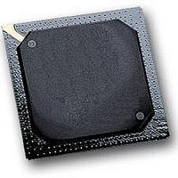
MPC564CZP40 Freescale Semiconductor, MPC564CZP40 Datasheet - Page 34

MPC564CZP40
Manufacturer Part Number
MPC564CZP40
Description
IC MPU 32BIT W/CODE COMP 388PBGA
Manufacturer
Freescale Semiconductor
Series
MPC5xxr
Specifications of MPC564CZP40
Core Processor
PowerPC
Core Size
32-Bit
Speed
40MHz
Connectivity
CAN, EBI/EMI, SCI, SPI, UART/USART
Peripherals
POR, PWM, WDT
Number Of I /o
56
Program Memory Size
512KB (512K x 8)
Program Memory Type
FLASH
Ram Size
32K x 8
Voltage - Supply (vcc/vdd)
2.5 V ~ 2.7 V
Data Converters
A/D 32x10b
Oscillator Type
External
Operating Temperature
-40°C ~ 85°C
Package / Case
388-BGA
Processor Series
MPC5xx
Core
PowerPC
Data Bus Width
32 bit
Data Ram Size
32 KB
Interface Type
CAN, JTAG, QSPI, SCI, SPI, UART
Maximum Clock Frequency
40 MHz
Number Of Programmable I/os
56
Number Of Timers
2
Operating Supply Voltage
0 V to 5 V
Maximum Operating Temperature
+ 85 C
Mounting Style
SMD/SMT
Minimum Operating Temperature
- 40 C
On-chip Adc
2 (10 bit, 32 Channel)
For Use With
MPC564EVB - KIT EVAL FOR MPC561/562/563/564
Lead Free Status / RoHS Status
Contains lead / RoHS non-compliant
Eeprom Size
-
Lead Free Status / Rohs Status
No
Available stocks
Company
Part Number
Manufacturer
Quantity
Price
Company:
Part Number:
MPC564CZP40
Manufacturer:
Freescale Semiconductor
Quantity:
10 000
- Current page: 34 of 1420
- Download datasheet (11Mb)
24.14
24.14.1
24.14.1.1
24.14.1.2
24.14.1.3
24.14.1.4
24.14.2
24.14.2.1
24.14.2.2
24.14.2.3
24.14.2.4
24.14.3
24.14.4
24.15
24.15.1
24.15.2
25.1
25.1.1
25.1.2
25.1.2.1
25.1.2.2
25.1.3
25.1.3.1
25.1.3.2
25.1.3.3
25.1.3.4
25.1.4
25.2
25.2.1
25.2.2
A.1
A.2
xxxiv
Paragraph
Number
IEEE 1149.1 Test Access Port ...................................................................................... 25-1
MPC561/MPC563 Restrictions .................................................................................. 25-32
ICDU Key Features ........................................................................................................ A-1
Class-Based Compression Model Main Principles......................................................... A-1
RCPU Development Access ...................................................................................... 24-76
Power Management ................................................................................................... 24-86
RCPU Development Access Messaging ................................................................. 24-77
RCPU Development Access Operation .................................................................. 24-79
Throughput .............................................................................................................. 24-82
Development Access Timing Diagrams ................................................................. 24-82
Functional Description ............................................................................................ 24-86
Low Power Modes .................................................................................................. 24-86
Overview ................................................................................................................... 25-2
Entering JTAG Mode ................................................................................................ 25-3
Instruction Register ................................................................................................. 25-30
HI-Z ........................................................................................................................ 25-32
Non-Scan Chain Operation ..................................................................................... 25-32
BSDL Description ................................................................................................... 25-33
DSDI Message .................................................................................................... 24-77
DSDO Message .................................................................................................. 24-78
BDM Status Message ......................................................................................... 24-78
Error Message (Invalid Message) ....................................................................... 24-79
Enabling RCPU Development Access Via READI Signals ............................... 24-80
Entering Background Debug Mode (BDM) Via READI Signals ...................... 24-80
Non-Debug Mode Access of RCPU Development Access ................................ 24-80
RCPU Development Access Flow Diagram ....................................................... 24-81
TAP Controller ..................................................................................................... 25-4
Boundary Scan Register ....................................................................................... 25-4
EXTEST ............................................................................................................. 25-31
SAMPLE/PRELOAD ......................................................................................... 25-31
BYPASS ............................................................................................................. 25-31
CLAMP ............................................................................................................... 25-32
MPC562/MPC564 Compression Features
IEEE 1149.1-Compliant Interface (JTAG)
MPC561/MPC563 Reference Manual, Rev. 1.2
Contents
Appendix A
Chapter 25
Title
Freescale Semiconductor
Number
Page
Related parts for MPC564CZP40
Image
Part Number
Description
Manufacturer
Datasheet
Request
R

Part Number:
Description:
MPC5 1K0 5%
Manufacturer:
TE Connectivity
Datasheet:

Part Number:
Description:
MPC5 500R 5%
Manufacturer:
TE Connectivity
Datasheet:

Part Number:
Description:
MPC5 5K0 5%
Manufacturer:
Tyco Electronics
Datasheet:

Part Number:
Description:
MPC5 5R0 5%
Manufacturer:
Tyco Electronics
Datasheet:

Part Number:
Description:
MPC5 50K 5%
Manufacturer:
Tyco Electronics
Datasheet:

Part Number:
Description:
MPC5 1R0 5%
Manufacturer:
Tyco Electronics
Datasheet:
Part Number:
Description:
Manufacturer:
Freescale Semiconductor, Inc
Datasheet:
Part Number:
Description:
Manufacturer:
Freescale Semiconductor, Inc
Datasheet:
Part Number:
Description:
Manufacturer:
Freescale Semiconductor, Inc
Datasheet:
Part Number:
Description:
Manufacturer:
Freescale Semiconductor, Inc
Datasheet:
Part Number:
Description:
Manufacturer:
Freescale Semiconductor, Inc
Datasheet:


