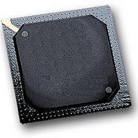
MPC564CZP40 Freescale Semiconductor, MPC564CZP40 Datasheet - Page 81

MPC564CZP40
Manufacturer Part Number
MPC564CZP40
Description
IC MPU 32BIT W/CODE COMP 388PBGA
Manufacturer
Freescale Semiconductor
Series
MPC5xxr
Specifications of MPC564CZP40
Core Processor
PowerPC
Core Size
32-Bit
Speed
40MHz
Connectivity
CAN, EBI/EMI, SCI, SPI, UART/USART
Peripherals
POR, PWM, WDT
Number Of I /o
56
Program Memory Size
512KB (512K x 8)
Program Memory Type
FLASH
Ram Size
32K x 8
Voltage - Supply (vcc/vdd)
2.5 V ~ 2.7 V
Data Converters
A/D 32x10b
Oscillator Type
External
Operating Temperature
-40°C ~ 85°C
Package / Case
388-BGA
Processor Series
MPC5xx
Core
PowerPC
Data Bus Width
32 bit
Data Ram Size
32 KB
Interface Type
CAN, JTAG, QSPI, SCI, SPI, UART
Maximum Clock Frequency
40 MHz
Number Of Programmable I/os
56
Number Of Timers
2
Operating Supply Voltage
0 V to 5 V
Maximum Operating Temperature
+ 85 C
Mounting Style
SMD/SMT
Minimum Operating Temperature
- 40 C
On-chip Adc
2 (10 bit, 32 Channel)
For Use With
MPC564EVB - KIT EVAL FOR MPC561/562/563/564
Lead Free Status / RoHS Status
Contains lead / RoHS non-compliant
Eeprom Size
-
Lead Free Status / Rohs Status
No
Available stocks
Company
Part Number
Manufacturer
Quantity
Price
Company:
Part Number:
MPC564CZP40
Manufacturer:
Freescale Semiconductor
Quantity:
10 000
- Current page: 81 of 1420
- Download datasheet (11Mb)
ACTIVE_HIGH
ACTIVE_LOW
0x0
0b0
italics
REG[FIELD]
x
n
¬
&
|
Logic level one
Logic level zero
To set a bit or bits
To clear a bit or bits
LSB
MSB
Asserted
Negated
Notational Conventions
Table i
Freescale Semiconductor
contains notational conventions that are used in this document.
Names for signals that are active high are shown in uppercase text. Signals that are
active high are referred to as asserted when they are high and negated when they
are low.
Names for signals that are active low are shown in uppercase text with an overbar.
Active-low signals are referred to as asserted (active) when they are low and
negated when they are high.
Prefix to denote hexadecimal number
Prefix to denote binary number
Italics indicate variable command parameters.
Book titles in text are also set in italics.
Abbreviations for registers are shown in uppercase. Specific bits, fields, or ranges
appear in brackets. For example, CRAMMCR[DIS] identifies the array disable bit
(DIS) within the CALRAM module configuration register.
A range of bits or signals is referred to by mnemonic and the numbers that define
the range. For example, DATA[24:31] form the least significant byte of the data
bus.
In some contexts, such as signal encodings, x indicates a don’t care.
Used to express an undefined numerical value
NOT logical operator
AND logical operator
OR logical operator
means to establish logic level one on the bit or bits.
means to establish logic level zero on the bit or bits.
means least significant bit or bits.
means most significant bit or bits.
means that a signal is in active logic state. An active low signal changes from logic
level one to logic level zero when asserted, and an active high signal changes from
logic level zero to logic level one.
means that an asserted signal changes logic state. An active low signal changes
from logic level zero to logic level one when negated, and an active high signal
changes from logic level one to logic level zero.
is the voltage that corresponds to Boolean true (1) state.
is the voltage that corresponds to Boolean false (0) state.
MPC561/MPC563 Reference Manual, Rev. 1.2
lxxxi
Related parts for MPC564CZP40
Image
Part Number
Description
Manufacturer
Datasheet
Request
R

Part Number:
Description:
MPC5 1K0 5%
Manufacturer:
TE Connectivity
Datasheet:

Part Number:
Description:
MPC5 500R 5%
Manufacturer:
TE Connectivity
Datasheet:

Part Number:
Description:
MPC5 5K0 5%
Manufacturer:
Tyco Electronics
Datasheet:

Part Number:
Description:
MPC5 5R0 5%
Manufacturer:
Tyco Electronics
Datasheet:

Part Number:
Description:
MPC5 50K 5%
Manufacturer:
Tyco Electronics
Datasheet:

Part Number:
Description:
MPC5 1R0 5%
Manufacturer:
Tyco Electronics
Datasheet:
Part Number:
Description:
Manufacturer:
Freescale Semiconductor, Inc
Datasheet:
Part Number:
Description:
Manufacturer:
Freescale Semiconductor, Inc
Datasheet:
Part Number:
Description:
Manufacturer:
Freescale Semiconductor, Inc
Datasheet:
Part Number:
Description:
Manufacturer:
Freescale Semiconductor, Inc
Datasheet:
Part Number:
Description:
Manufacturer:
Freescale Semiconductor, Inc
Datasheet:


