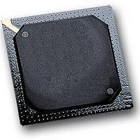
MPC564CZP40 Freescale Semiconductor, MPC564CZP40 Datasheet - Page 921

MPC564CZP40
Manufacturer Part Number
MPC564CZP40
Description
IC MPU 32BIT W/CODE COMP 388PBGA
Manufacturer
Freescale Semiconductor
Series
MPC5xxr
Specifications of MPC564CZP40
Core Processor
PowerPC
Core Size
32-Bit
Speed
40MHz
Connectivity
CAN, EBI/EMI, SCI, SPI, UART/USART
Peripherals
POR, PWM, WDT
Number Of I /o
56
Program Memory Size
512KB (512K x 8)
Program Memory Type
FLASH
Ram Size
32K x 8
Voltage - Supply (vcc/vdd)
2.5 V ~ 2.7 V
Data Converters
A/D 32x10b
Oscillator Type
External
Operating Temperature
-40°C ~ 85°C
Package / Case
388-BGA
Processor Series
MPC5xx
Core
PowerPC
Data Bus Width
32 bit
Data Ram Size
32 KB
Interface Type
CAN, JTAG, QSPI, SCI, SPI, UART
Maximum Clock Frequency
40 MHz
Number Of Programmable I/os
56
Number Of Timers
2
Operating Supply Voltage
0 V to 5 V
Maximum Operating Temperature
+ 85 C
Mounting Style
SMD/SMT
Minimum Operating Temperature
- 40 C
On-chip Adc
2 (10 bit, 32 Channel)
For Use With
MPC564EVB - KIT EVAL FOR MPC561/562/563/564
Lead Free Status / RoHS Status
Contains lead / RoHS non-compliant
Eeprom Size
-
Lead Free Status / Rohs Status
No
Available stocks
Company
Part Number
Manufacturer
Quantity
Price
Company:
Part Number:
MPC564CZP40
Manufacturer:
Freescale Semiconductor
Quantity:
10 000
- Current page: 921 of 1420
- Download datasheet (11Mb)
sampling the value of the status pins (VF and VFLS), and the address of the cycles marked as program
trace cycle immediately after the VSYNC report on the VF pins.
The last two instructions reported on the VF pins are not always valid. Therefore at the last stage of the
reconstruction software, the last two instructions should be ignored.
23.1.4.5
In order to store all the information generated on the pins during program trace (five bits per clock + 30
bits per show cycle) a large memory buffer may be needed. However, since this information includes
events that were canceled, compression can be very effective. External hardware can be added to eliminate
all canceled instructions and report only on branches (taken and not taken), indirect flow change, and the
number of sequential instructions after the last flow change.
23.1.5
Instruction fetch show cycles are controlled by the bits in the ICTRL and the state of VSYNC. The
following table defines the level of fetch show cycles generated by the CPU. For information on the fetch
show cycles control bits refer to
23.2
Watchpoints, when detected, are reported to the external world on dedicated pins but do not change the
timing and the flow of the machine. Breakpoints, when detected, force the machine to branch to the
appropriate exception handler. The RCPU supports internal watchpoints, internal breakpoints, and
external breakpoints.
Internal watchpoints are generated when a user programmable set of conditions are met. Internal
breakpoints can be programmed to be generated either as an immediate result of the assertion of one of the
internal watchpoints, or after an internal watchpoint is asserted for a user programmable times.
Programming a certain internal watchpoint to generate an internal breakpoint can be done either in
Freescale Semiconductor
Watchpoints and Breakpoints Support
Instruction Fetch Show Cycle Control
VSYNC
Compress
X
X
X
0
1
A cycle marked with the program trace cycle attribute is generated for any
change in the VSYNC state (assertion or negation).
Instruction Fetch Show Cycle
Control Bits
Table
MPC561/MPC563 Reference Manual, Rev. 1.2
Table 23-5. Fetch Show Cycles Control
ISCTL
00
01
10
11
11
23-5.
NOTE
All fetch cycles
All change of flow (direct & indirect)
All indirect change of flow
No show cycles are performed
All indirect change of flow
Show Cycles Generated
Development Support
23-7
Related parts for MPC564CZP40
Image
Part Number
Description
Manufacturer
Datasheet
Request
R

Part Number:
Description:
MPC5 1K0 5%
Manufacturer:
TE Connectivity
Datasheet:

Part Number:
Description:
MPC5 500R 5%
Manufacturer:
TE Connectivity
Datasheet:

Part Number:
Description:
MPC5 5K0 5%
Manufacturer:
Tyco Electronics
Datasheet:

Part Number:
Description:
MPC5 5R0 5%
Manufacturer:
Tyco Electronics
Datasheet:

Part Number:
Description:
MPC5 50K 5%
Manufacturer:
Tyco Electronics
Datasheet:

Part Number:
Description:
MPC5 1R0 5%
Manufacturer:
Tyco Electronics
Datasheet:
Part Number:
Description:
Manufacturer:
Freescale Semiconductor, Inc
Datasheet:
Part Number:
Description:
Manufacturer:
Freescale Semiconductor, Inc
Datasheet:
Part Number:
Description:
Manufacturer:
Freescale Semiconductor, Inc
Datasheet:
Part Number:
Description:
Manufacturer:
Freescale Semiconductor, Inc
Datasheet:
Part Number:
Description:
Manufacturer:
Freescale Semiconductor, Inc
Datasheet:


