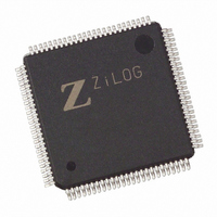
EZ80F92AZ020EG Zilog, EZ80F92AZ020EG Datasheet - Page 167

EZ80F92AZ020EG
Manufacturer Part Number
EZ80F92AZ020EG
Description
IC ACCLAIM MCU 128KB 100LQFP
Manufacturer
Zilog
Series
eZ80® Acclaim!®r
Specifications of EZ80F92AZ020EG
Core Processor
Z8
Core Size
8-Bit
Speed
20MHz
Connectivity
I²C, IrDA, SPI, UART/USART
Peripherals
Brown-out Detect/Reset, POR, WDT
Number Of I /o
24
Program Memory Size
128KB (128K x 8)
Program Memory Type
FLASH
Ram Size
8K x 8
Voltage - Supply (vcc/vdd)
3 V ~ 3.6 V
Oscillator Type
Internal
Operating Temperature
-40°C ~ 105°C
Package / Case
100-LQFP
Processor Series
EZ80F92x
Core
eZ80
Data Bus Width
8 bit
Data Ram Size
8 KB
Interface Type
I2C, IrDA, SPI, UART
Maximum Clock Frequency
20 MHz
Number Of Programmable I/os
24
Number Of Timers
6
Operating Supply Voltage
3 V to 3.6 V
Maximum Operating Temperature
+ 105 C
Mounting Style
SMD/SMT
Development Tools By Supplier
eZ80F920200ZCOG
Minimum Operating Temperature
- 40 C
Lead Free Status / RoHS Status
Lead free / RoHS Compliant
Eeprom Size
-
Data Converters
-
Lead Free Status / Rohs Status
Details
Other names
269-3871
EZ80F92AZ020EG
EZ80F92AZ020EG
Available stocks
Company
Part Number
Manufacturer
Quantity
Price
- Current page: 167 of 261
- Download datasheet (4Mb)
PS015313-0508
I
The I2C_CCR register is a Write Only register. The seven LSBs control the frequency at
which the I
is in MASTER mode. The Write Only I2C_CCR registers share the same I/O addresses as
the Read Only I2C_SR registers. See
Table 90. I
The I
clock is f
In MASTER mode, the I
The use of two separately-programmable dividers allows the MASTER mode output fre-
quency to be set independently of the frequency at which the I
ture is particularly useful in multimaster systems because the frequency at which the I
bus is sampled must be at least 10 times the frequency of the fastest master on the bus to
ensure that START and STOP conditions are always detected. By using two programma-
ble clock divider stages, a high sampling frequency can be ensured while allowing the
MASTER mode output to be set to a lower frequency.
Bit
Reset
CPU Access
Note: W = Read only.
Bit
Position
7
[6:3]
M
[2:0]
N
f
f
2
SAMP
SCL
C Clock Control Register
2
=
C clocks are derived from the CPU system clock. The frequency of the CPU system
=
SCK
10 • (M + 1)(2)
2
2
C Clock Control Registers(I2C_CCR = 00CCh)
C bus is sampled and the frequency of the I
f
. The I
SCLK
2
N
f
SCLK
2
Value Description
0
0000–
1111
000–
111
C bus is sampled by the I
N
2
C clock output frequency on SCL (f
W
Reserved.
I
I
7
0
2
2
C clock divider scalar value.
C clock divider exponent.
W
6
0
Table
90.
W
5
0
2
C block at the frequency f
W
4
0
2
C clock line (SCL) when the I
W
3
0
SCL
2
C bus is sampled. This fea-
Product Specification
) is supplied by:
W
2
0
I2C Serial I/O Interface
SAMP
W
1
0
supplied by:
W
0
0
2
2
C
C
160
Related parts for EZ80F92AZ020EG
Image
Part Number
Description
Manufacturer
Datasheet
Request
R

Part Number:
Description:
Communication Controllers, ZILOG INTELLIGENT PERIPHERAL CONTROLLER (ZIP)
Manufacturer:
Zilog, Inc.
Datasheet:

Part Number:
Description:
KIT DEV FOR Z8 ENCORE 16K TO 64K
Manufacturer:
Zilog
Datasheet:

Part Number:
Description:
KIT DEV Z8 ENCORE XP 28-PIN
Manufacturer:
Zilog
Datasheet:

Part Number:
Description:
DEV KIT FOR Z8 ENCORE 8K/4K
Manufacturer:
Zilog
Datasheet:

Part Number:
Description:
KIT DEV Z8 ENCORE XP 28-PIN
Manufacturer:
Zilog
Datasheet:

Part Number:
Description:
DEV KIT FOR Z8 ENCORE 4K TO 8K
Manufacturer:
Zilog
Datasheet:

Part Number:
Description:
CMOS Z8 microcontroller. ROM 16 Kbytes, RAM 256 bytes, speed 16 MHz, 32 lines I/O, 3.0V to 5.5V
Manufacturer:
Zilog, Inc.
Datasheet:

Part Number:
Description:
Low-cost microcontroller. 512 bytes ROM, 61 bytes RAM, 8 MHz
Manufacturer:
Zilog, Inc.
Datasheet:

Part Number:
Description:
Z8 4K OTP Microcontroller
Manufacturer:
Zilog, Inc.
Datasheet:

Part Number:
Description:
CMOS SUPER8 ROMLESS MCU
Manufacturer:
Zilog, Inc.
Datasheet:

Part Number:
Description:
SL1866 CMOSZ8 OTP Microcontroller
Manufacturer:
Zilog, Inc.
Datasheet:

Part Number:
Description:
SL1866 CMOSZ8 OTP Microcontroller
Manufacturer:
Zilog, Inc.
Datasheet:

Part Number:
Description:
OTP (KB) = 1, RAM = 125, Speed = 12, I/O = 14, 8-bit Timers = 2, Comm Interfaces Other Features = Por, LV Protect, Voltage = 4.5-5.5V
Manufacturer:
Zilog, Inc.
Datasheet:

Part Number:
Description:
Manufacturer:
Zilog, Inc.
Datasheet:


