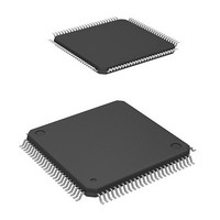
HD64F2239TF20I Renesas Electronics America, HD64F2239TF20I Datasheet - Page 26

HD64F2239TF20I
Manufacturer Part Number
HD64F2239TF20I
Description
MCU 3V 384K I-TEMP 100-TQFP
Manufacturer
Renesas Electronics America
Series
H8® H8S/2200r
Datasheet
1.DF2238RFA6V.pdf
(1048 pages)
Specifications of HD64F2239TF20I
Core Processor
H8S/2000
Core Size
16-Bit
Speed
20MHz
Connectivity
I²C, SCI, SmartCard
Peripherals
DMA, POR, PWM, WDT
Number Of I /o
72
Program Memory Size
384KB (384K x 8)
Program Memory Type
FLASH
Ram Size
32K x 8
Voltage - Supply (vcc/vdd)
2.7 V ~ 3.6 V
Data Converters
A/D 8x10b; D/A 2x8b
Oscillator Type
Internal
Operating Temperature
-40°C ~ 85°C
Package / Case
100-TQFP, 100-VQFP
Lead Free Status / RoHS Status
Contains lead / RoHS non-compliant
Eeprom Size
-
Available stocks
Company
Part Number
Manufacturer
Quantity
Price
Company:
Part Number:
HD64F2239TF20I
Manufacturer:
Renesas Electronics America
Quantity:
10 000
- Current page: 26 of 1048
- Download datasheet (6Mb)
Section 7 Bus Controller....................................................................................165
7.1
7.2
7.3
7.4
7.5
7.6
7.7
7.8
7.9
7.10 Bus Arbitration.................................................................................................................. 199
Rev. 6.00 Mar. 18, 2010 Page xxiv of lx
REJ09B0054-0600
6.4.3
6.4.4
6.4.5
6.4.6
6.4.7
6.4.8
Features............................................................................................................................. 165
Input/Output Pins .............................................................................................................. 167
Register Descriptions ........................................................................................................ 167
7.3.1
7.3.2
7.3.3
7.3.4
7.3.5
7.3.6
Bus Control ....................................................................................................................... 175
7.4.1
7.4.2
7.4.3
7.4.4
Basic Timing..................................................................................................................... 178
7.5.1
7.5.2
7.5.3
Basic Bus Interface ........................................................................................................... 181
7.6.1
7.6.2
7.6.3
7.6.4
Burst ROM Interface......................................................................................................... 192
7.7.1
7.7.2
Idle Cycle.......................................................................................................................... 194
Bus Release....................................................................................................................... 197
7.9.1
CMFA and CMFB ............................................................................................... 163
PC Break Interrupt when DTC and DMAC Is Bus Master .................................. 163
PC Break Set for Instruction Fetch at Address Following BSR, JSR, JMP,
TRAPA, RTE, and RTS Instruction..................................................................... 163
I Bit Set by LDC, ANDC, ORC, and XORC Instruction..................................... 164
PC Break Set for Instruction Fetch at Address Following Bcc Instruction.......... 164
PC Break Set for Instruction Fetch at Branch Destination Address of Bcc
Instruction ............................................................................................................ 164
Bus Width Control Register (ABWCR)............................................................... 168
Access State Control Register (ASTCR) ............................................................. 168
Wait Control Registers H and L (WCRH, WCRL).............................................. 169
Bus Control Register H (BCRH) ......................................................................... 172
Bus Control Register L (BCRL) .......................................................................... 173
Pin Function Control Register (PFCR) ................................................................ 174
Area Divisions ..................................................................................................... 175
Bus Specifications................................................................................................ 176
Bus Interface for Each Area................................................................................. 177
Chip Select Signals .............................................................................................. 178
On-Chip Memory (ROM, RAM) Access Timing ................................................ 179
On-Chip Peripheral Module Access Timing........................................................ 180
External Address Space Access Timing .............................................................. 181
Data Size and Data Alignment............................................................................. 181
Valid Strobes........................................................................................................ 182
Basic Timing........................................................................................................ 183
Wait Control ........................................................................................................ 190
Basic Timing........................................................................................................ 192
Wait Control ........................................................................................................ 194
Bus Release Usage Note ...................................................................................... 198
Related parts for HD64F2239TF20I
Image
Part Number
Description
Manufacturer
Datasheet
Request
R

Part Number:
Description:
KIT STARTER FOR M16C/29
Manufacturer:
Renesas Electronics America
Datasheet:

Part Number:
Description:
KIT STARTER FOR R8C/2D
Manufacturer:
Renesas Electronics America
Datasheet:

Part Number:
Description:
R0K33062P STARTER KIT
Manufacturer:
Renesas Electronics America
Datasheet:

Part Number:
Description:
KIT STARTER FOR R8C/23 E8A
Manufacturer:
Renesas Electronics America
Datasheet:

Part Number:
Description:
KIT STARTER FOR R8C/25
Manufacturer:
Renesas Electronics America
Datasheet:

Part Number:
Description:
KIT STARTER H8S2456 SHARPE DSPLY
Manufacturer:
Renesas Electronics America
Datasheet:

Part Number:
Description:
KIT STARTER FOR R8C38C
Manufacturer:
Renesas Electronics America
Datasheet:

Part Number:
Description:
KIT STARTER FOR R8C35C
Manufacturer:
Renesas Electronics America
Datasheet:

Part Number:
Description:
KIT STARTER FOR R8CL3AC+LCD APPS
Manufacturer:
Renesas Electronics America
Datasheet:

Part Number:
Description:
KIT STARTER FOR RX610
Manufacturer:
Renesas Electronics America
Datasheet:

Part Number:
Description:
KIT STARTER FOR R32C/118
Manufacturer:
Renesas Electronics America
Datasheet:

Part Number:
Description:
KIT DEV RSK-R8C/26-29
Manufacturer:
Renesas Electronics America
Datasheet:

Part Number:
Description:
KIT STARTER FOR SH7124
Manufacturer:
Renesas Electronics America
Datasheet:

Part Number:
Description:
KIT STARTER FOR H8SX/1622
Manufacturer:
Renesas Electronics America
Datasheet:

Part Number:
Description:
KIT DEV FOR SH7203
Manufacturer:
Renesas Electronics America
Datasheet:


