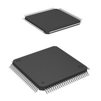
HD64F2239TF20I Renesas Electronics America, HD64F2239TF20I Datasheet - Page 745

HD64F2239TF20I
Manufacturer Part Number
HD64F2239TF20I
Description
MCU 3V 384K I-TEMP 100-TQFP
Manufacturer
Renesas Electronics America
Series
H8® H8S/2200r
Datasheet
1.DF2238RFA6V.pdf
(1048 pages)
Specifications of HD64F2239TF20I
Core Processor
H8S/2000
Core Size
16-Bit
Speed
20MHz
Connectivity
I²C, SCI, SmartCard
Peripherals
DMA, POR, PWM, WDT
Number Of I /o
72
Program Memory Size
384KB (384K x 8)
Program Memory Type
FLASH
Ram Size
32K x 8
Voltage - Supply (vcc/vdd)
2.7 V ~ 3.6 V
Data Converters
A/D 8x10b; D/A 2x8b
Oscillator Type
Internal
Operating Temperature
-40°C ~ 85°C
Package / Case
100-TQFP, 100-VQFP
Lead Free Status / RoHS Status
Contains lead / RoHS non-compliant
Eeprom Size
-
Available stocks
Company
Part Number
Manufacturer
Quantity
Price
Company:
Part Number:
HD64F2239TF20I
Manufacturer:
Renesas Electronics America
Quantity:
10 000
- Current page: 745 of 1048
- Download datasheet (6Mb)
11. Notes on ICDR Reads and ICCR Access in Slave Transmit Mode
TRS bit
In a transmit operation in the slave mode of the I
or read or write to the ICCR register during the period indicated by the shaded portion in figure
16.25.
Normally, when interrupt processing is triggered in synchronization with the rising edge of the
9th clock cycle, the period in question has already elapsed when the transition to interrupt
processing takes place, so there is no problem with reading the ICDR register or reading or
writing to the ICCR register.
To ensure that the interrupt processing is performed properly, one of the following two
conditions should be applied.
(1) Make sure that reading received data from the ICDR register, or reading or writing to the
(2) Monitor the BC2 to BC0 counter in the ICMR register and, when the value of BC2 to BC0
SDA
SCL
ICCR register, is completed before the next slave address receive operation starts.
is 000 (8th or 9th clock cycle), allow a waiting time of at least 2 transfer clock cycles in
order to involve the problem period in question before reading from the ICDR register, or
reading or writing to the ICCR register.
Figure 16.25 ICDR Read and ICCR Access Timing in Slave Transmit Mode
Address received
R/W
8
Detection of 9th clock
cycle rising edge
A
9
Period when ICDR reads and ICCR
reads and writes are prohibited
(6 system clock cycles)
2
Waveforms if
problem occurs
C bus interface, do not read the ICDR register
Section 16 I
Rev. 6.00 Mar. 18, 2010 Page 683 of 982
2
C Bus Interface (IIC) (Option)
REJ09B0054-0600
Data transmission
Bit 7
ICDR write
Related parts for HD64F2239TF20I
Image
Part Number
Description
Manufacturer
Datasheet
Request
R

Part Number:
Description:
KIT STARTER FOR M16C/29
Manufacturer:
Renesas Electronics America
Datasheet:

Part Number:
Description:
KIT STARTER FOR R8C/2D
Manufacturer:
Renesas Electronics America
Datasheet:

Part Number:
Description:
R0K33062P STARTER KIT
Manufacturer:
Renesas Electronics America
Datasheet:

Part Number:
Description:
KIT STARTER FOR R8C/23 E8A
Manufacturer:
Renesas Electronics America
Datasheet:

Part Number:
Description:
KIT STARTER FOR R8C/25
Manufacturer:
Renesas Electronics America
Datasheet:

Part Number:
Description:
KIT STARTER H8S2456 SHARPE DSPLY
Manufacturer:
Renesas Electronics America
Datasheet:

Part Number:
Description:
KIT STARTER FOR R8C38C
Manufacturer:
Renesas Electronics America
Datasheet:

Part Number:
Description:
KIT STARTER FOR R8C35C
Manufacturer:
Renesas Electronics America
Datasheet:

Part Number:
Description:
KIT STARTER FOR R8CL3AC+LCD APPS
Manufacturer:
Renesas Electronics America
Datasheet:

Part Number:
Description:
KIT STARTER FOR RX610
Manufacturer:
Renesas Electronics America
Datasheet:

Part Number:
Description:
KIT STARTER FOR R32C/118
Manufacturer:
Renesas Electronics America
Datasheet:

Part Number:
Description:
KIT DEV RSK-R8C/26-29
Manufacturer:
Renesas Electronics America
Datasheet:

Part Number:
Description:
KIT STARTER FOR SH7124
Manufacturer:
Renesas Electronics America
Datasheet:

Part Number:
Description:
KIT STARTER FOR H8SX/1622
Manufacturer:
Renesas Electronics America
Datasheet:

Part Number:
Description:
KIT DEV FOR SH7203
Manufacturer:
Renesas Electronics America
Datasheet:


