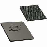
EP1S40B956C5 Altera, EP1S40B956C5 Datasheet - Page 759

EP1S40B956C5
Manufacturer Part Number
EP1S40B956C5
Description
IC STRATIX FPGA 40K LE 956-BGA
Manufacturer
Altera
Series
Stratix®r
Datasheet
1.EP1S10F484I6N.pdf
(864 pages)
Specifications of EP1S40B956C5
Number Of Logic Elements/cells
41250
Number Of Labs/clbs
4125
Total Ram Bits
3423744
Number Of I /o
683
Voltage - Supply
1.425 V ~ 1.575 V
Mounting Type
Surface Mount
Operating Temperature
0°C ~ 85°C
Package / Case
956-BGA
Lead Free Status / RoHS Status
Contains lead / RoHS non-compliant
Number Of Gates
-
Available stocks
Company
Part Number
Manufacturer
Quantity
Price
Part Number:
EP1S40B956C5
Manufacturer:
ALTERA/阿尔特拉
Quantity:
20 000
- Current page: 759 of 864
- Download datasheet (11Mb)
Altera Corporation
July 2005
The Quartus II software verifies successful JTAG configuration upon
completion. The software checks the state of CONF_DONE through the
JTAG port. If CONF_DONE is not in the correct state, the Quartus II
software indicates that configuration has failed. If CONF_DONE is in the
correct state, the software indicates that configuration was successful.
1
Do not attempt JTAG and non-JTAG configuration simultaneously. When
configuring through JTAG, allow any non-JTAG configuration to
complete first.
Figure 11–22
device with a microprocessor.
Figure 11–22. JTAG Configuration of Stratix & Stratix GX Devices with a
Microprocessor
Notes to
(1)
(2)
Configuration with JRunner Software Driver
JRunner is a software driver that allows you to configure Altera FPGAs
through the ByteBlasterMV download cable in JTAG mode. The
programming input file supported is in Raw Binary File (.rbf) format.
JRunner also requires a Chain Description File (.cdf) generated by the
Quartus II software. JRunner is targeted for embedded JTAG
configuration. The source code has been developed for the Windows NT
operating system. You can customize the code to make it run on other
platforms.
Connect the nCONFIG, MSEL2, MSEL1, and MSEL0 pins to support a non-JTAG
configuration scheme. If your design only uses JTAG configuration, connect the
nCONFIG pin to V
Pull DATA0 and DCLK to either high or low.
Microprocessor
Figure
If VCCIO is tied to 3.3 V, both the I/O pins and JTAG TDO port
drive at 3.3-V levels.
ADDR
shows the JTAG configuration of a Stratix or Stratix GX
11–22:
Memory
CC
DATA
and the MSEL2, MSEL1, and MSEL0 pins to ground.
(1)
(2)
(2)
Configuring Stratix & Stratix GX Devices
Stratix GX Device
nCONFIG
DATA0
DCLK
TDI
TCK
TMS
Stratix Device Handbook, Volume 2
Stratix or
CONF_DONE
nSTATUS
MSEL2
MSEL1
MSEL0
TDO
V CC
(1)
(1)
(1)
10 kΩ
V CC
10 kΩ
11–41
Related parts for EP1S40B956C5
Image
Part Number
Description
Manufacturer
Datasheet
Request
R

Part Number:
Description:
CYCLONE II STARTER KIT EP2C20N
Manufacturer:
Altera
Datasheet:

Part Number:
Description:
CPLD, EP610 Family, ECMOS Process, 300 Gates, 16 Macro Cells, 16 Reg., 16 User I/Os, 5V Supply, 35 Speed Grade, 24DIP
Manufacturer:
Altera Corporation
Datasheet:

Part Number:
Description:
CPLD, EP610 Family, ECMOS Process, 300 Gates, 16 Macro Cells, 16 Reg., 16 User I/Os, 5V Supply, 15 Speed Grade, 24DIP
Manufacturer:
Altera Corporation
Datasheet:

Part Number:
Description:
Manufacturer:
Altera Corporation
Datasheet:

Part Number:
Description:
CPLD, EP610 Family, ECMOS Process, 300 Gates, 16 Macro Cells, 16 Reg., 16 User I/Os, 5V Supply, 30 Speed Grade, 24DIP
Manufacturer:
Altera Corporation
Datasheet:

Part Number:
Description:
High-performance, low-power erasable programmable logic devices with 8 macrocells, 10ns
Manufacturer:
Altera Corporation
Datasheet:

Part Number:
Description:
High-performance, low-power erasable programmable logic devices with 8 macrocells, 7ns
Manufacturer:
Altera Corporation
Datasheet:

Part Number:
Description:
Classic EPLD
Manufacturer:
Altera Corporation
Datasheet:

Part Number:
Description:
High-performance, low-power erasable programmable logic devices with 8 macrocells, 10ns
Manufacturer:
Altera Corporation
Datasheet:

Part Number:
Description:
Manufacturer:
Altera Corporation
Datasheet:

Part Number:
Description:
Manufacturer:
Altera Corporation
Datasheet:

Part Number:
Description:
Manufacturer:
Altera Corporation
Datasheet:

Part Number:
Description:
CPLD, EP610 Family, ECMOS Process, 300 Gates, 16 Macro Cells, 16 Reg., 16 User I/Os, 5V Supply, 25 Speed Grade, 24DIP
Manufacturer:
Altera Corporation
Datasheet:


