IPR-HPMCII Altera, IPR-HPMCII Datasheet - Page 135
IPR-HPMCII
Manufacturer Part Number
IPR-HPMCII
Description
IP CORE Renewal Of IP-HPMCII
Manufacturer
Altera
Datasheet
1.IP-HPMCII.pdf
(176 pages)
Specifications of IPR-HPMCII
Software Application
IP CORE, Memory Controllers, SDRAM
Supported Families
Arria II GX, HardCopy III, Stratix III, Stratix IV
Core Architecture
FPGA
Core Sub-architecture
Arria, HardCopy, Stratix
Rohs Compliant
NA
Lead Free Status / RoHS Status
na


Chapter 7: Functional Description—High-Performance Controller II
Register Maps Description
Table 7–10. Address 0x005 Mode Register 0-1 (Part 1 of 2)
December 2010 Altera Corporation
15:13
21:19
11:9
Bit
2:0
6:4
12
16
17
18
3
7
8
ALTMEMPHY Register Map
Burst length
BT
CAS latency
Reserved
DLL
Write recovery
PD
Reserved
DLL
ODS
RTT
AL
1
Name
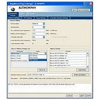
The ALTMEMPHY register map allows you to control the memory components’
mode register settings. To access the ALTMEMPHY register map, connect the
ALTMEMPHY Debug interface signals in
After configuring the ALTMEMPHY register map, initialize a calibration request by
setting bit 2 in the CSR register map address 0x100
settings to take effect.
DDR3 SDRAM with leveling does not support the ALTMEMPHY register map. For
more information about DDR3 SDRAM with leveling, refer to
Leveling” on page
Default
0/1
—
—
—
8
0
0
0
0
0
0
0
5–7.
Access
RW
RW
RW
RW
RW
RW
RW
RO
RO
RO
—
—
Section II. DDR3 SDRAM Controller with ALTMEMPHY IP User Guide
This value is set to 8 because the DDR3 SDRAM
HPC II only supports a burst length of 8.
This value is set to 0 because DDR3 SDRAM
SDRAM HPC II only supports sequential bursts.
CAS latency setting. The default value for these bits
is set by the MegaWizard CAS Latency setting for
your controller instance. You must set this value in
the CSR interface register map 0x126
as well.
Reserved for future use.
Not used by the controller, but you can set and
programm into the memory device mode register.
Write recovery (t
these bits is set by the MegaWizard Write Recovery
(t
set this value in CSR interface register map 0x126
(Table
This value is set to 0 because DDR3 SDRAM HPC II
only supports power-down fast exit mode.
Reserved for future use.
Not used by the controller, but you can set and
program into the memory device mode register.
Additive latency setting. The default value for these
bits is set by the MegaWizard Additive Latency
setting for your controller instance. You must set
this value in CSR interface register map 0x126
(Table
Table 7–8
WR
) setting for your controller instance. You must
7–20) as well.
7–20) as well.
(Table
using the Avalon-MM protocol.
External Memory Interface Handbook Volume 3
WR
7–12) for the mode register
Description
) setting. The default value for
“DDR3 SDRAM With
(Table
7–20)
7–19
Related parts for IPR-HPMCII
Image
Part Number
Description
Manufacturer
Datasheet
Request
R

Part Number:
Description:
IP NIOS II MEGACORE RENEW
Manufacturer:
Altera
Datasheet:
Part Number:
Description:
IP CORE Renewal Of IP-XAUIPCS
Manufacturer:
Altera
Datasheet:

Part Number:
Description:
IP CORE Renewal Of IP-10GETHERNET
Manufacturer:
Altera
Datasheet:
Part Number:
Description:
IP CORE Renewal Of IP-ASI
Manufacturer:
Altera
Datasheet:

Part Number:
Description:
IP CORE Renewal Of IP-CIC
Manufacturer:
Altera
Datasheet:

Part Number:
Description:
IP CORE Renewal Of IP-CRC
Manufacturer:
Altera
Datasheet:
Part Number:
Description:
IP CORE Renewal Of IP-ED8B10B
Manufacturer:
Altera
Datasheet:

Part Number:
Description:
CPLD, EP610 Family, ECMOS Process, 300 Gates, 16 Macro Cells, 16 Reg., 16 User I/Os, 5V Supply, 35 Speed Grade, 24DIP
Manufacturer:
Altera Corporation
Datasheet:
Part Number:
Description:
CPLD, EP610 Family, ECMOS Process, 300 Gates, 16 Macro Cells, 16 Reg., 16 User I/Os, 5V Supply, 15 Speed Grade, 24DIP
Manufacturer:
Altera Corporation
Datasheet:
Part Number:
Description:
Manufacturer:
Altera Corporation
Datasheet: