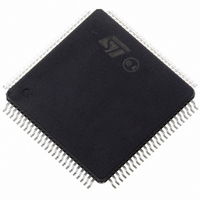
ST10F276Z5T3 STMicroelectronics, ST10F276Z5T3 Datasheet - Page 105

ST10F276Z5T3
Manufacturer Part Number
ST10F276Z5T3
Description
MCU 16BIT 832KBIT FLASH 144-TQFP
Manufacturer
STMicroelectronics
Series
ST10r
Datasheet
1.ST10F276Z5T3.pdf
(239 pages)
Specifications of ST10F276Z5T3
Core Processor
ST10
Core Size
16-Bit
Speed
40MHz
Connectivity
ASC, CAN, EBI/EMI, I²C, SSC, UART/USART
Peripherals
POR, PWM, WDT
Number Of I /o
111
Program Memory Size
832KB (832K x 8)
Program Memory Type
FLASH
Ram Size
68K x 8
Voltage - Supply (vcc/vdd)
4.5 V ~ 5.5 V
Data Converters
A/D 24x10b
Oscillator Type
Internal
Operating Temperature
-40°C ~ 125°C
Package / Case
144-TQFP, 144-VQFP
Cpu Family
ST10
Device Core Size
16b
Frequency (max)
40MHz
Interface Type
CAN/I2C
Total Internal Ram Size
68KB
# I/os (max)
111
Number Of Timers - General Purpose
5
Operating Supply Voltage (typ)
5V
Operating Supply Voltage (max)
5.5V
Operating Supply Voltage (min)
4.5V
On-chip Adc
24-chx10-bit
Instruction Set Architecture
CISC/RISC
Operating Temp Range
-40C to 125C
Operating Temperature Classification
Automotive
Mounting
Surface Mount
Pin Count
144
Package Type
LQFP
Processor Series
ST10F27x
Core
ST10
Data Bus Width
16 bit
Data Ram Size
68 KB
Maximum Clock Frequency
40 MHz
Number Of Programmable I/os
111
Number Of Timers
5
Maximum Operating Temperature
+ 125 C
Mounting Style
SMD/SMT
Minimum Operating Temperature
- 40 C
For Use With
497-6399 - KIT DEV STARTER ST10F276Z5
Lead Free Status / RoHS Status
Lead free / RoHS Compliant
Eeprom Size
-
Lead Free Status / Rohs Status
Compliant
Available stocks
Company
Part Number
Manufacturer
Quantity
Price
Company:
Part Number:
ST10F276Z5T3
Manufacturer:
STMicroelectronics
Quantity:
10 000
ST10F276Z5
18
Watchdog timer
The Watchdog Timer is a fail-safe mechanism which prevents the microcontroller from
malfunctioning for long periods of time.
The Watchdog Timer is always enabled after a reset of the chip and can only be disabled in
the time interval until the EINIT (end of initialization) instruction has been executed.
Therefore, the chip start-up procedure is always monitored. The software must be designed
to service the watchdog timer before it overflows. If, due to hardware or software related
failures, the software fails to do so, the watchdog timer overflows and generates an internal
hardware reset. It pulls the RSTOUT pin low in order to allow external hardware components
to be reset.
Each of the different reset sources is indicated in the WDTCON register:
●
●
●
The indicated bits are cleared with the EINIT instruction. The source of the reset can be
identified during the initialization phase.
The Watchdog Timer is 16-bit, clocked with the system clock divided by 2 or 128. The high
Byte of the watchdog timer register can be set to a pre-specified reload value (stored in
WDTREL).
Each time it is serviced by the application software, the high byte of the watchdog timer is
reloaded. For security, rewrite WDTCON each time before the watchdog timer is serviced
The
clock respectively.
Table 59.
Table 60.
Reload value in WDTREL
Reload value in WDTREL
Table 59
Watchdog Timer Reset in case of an overflow
Software Reset in case of execution of the SRST instruction
Short, Long and Power-On Reset in case of hardware reset (and depending of reset
pulse duration and RPD pin configuration)
WDTREL reload value (f
WDTREL reload value (f
FFh
FFh
00h
00h
and
Table 60
show the watchdog time range for 40 MHz and 64 MHz CPU
CPU
CPU
2 (WDTIN = ‘0’)
2 (WDTIN = ‘0’)
3.277 ms
2.048 ms
12.8 µs
= 40 MHz)
= 64 MHz)
8 µs
Prescaler for f
Prescaler for f
CPU
CPU
= 40 MHz
= 64 MHz
128 (WDTIN = ‘1’)
128 (WDTIN = ‘1’)
209.7 ms
131.1 ms
819.2 µs
512 µs
Watchdog timer
105/239


