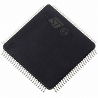
ST10F276Z5T3 STMicroelectronics, ST10F276Z5T3 Datasheet - Page 189

ST10F276Z5T3
Manufacturer Part Number
ST10F276Z5T3
Description
MCU 16BIT 832KBIT FLASH 144-TQFP
Manufacturer
STMicroelectronics
Series
ST10r
Datasheet
1.ST10F276Z5T3.pdf
(239 pages)
Specifications of ST10F276Z5T3
Core Processor
ST10
Core Size
16-Bit
Speed
40MHz
Connectivity
ASC, CAN, EBI/EMI, I²C, SSC, UART/USART
Peripherals
POR, PWM, WDT
Number Of I /o
111
Program Memory Size
832KB (832K x 8)
Program Memory Type
FLASH
Ram Size
68K x 8
Voltage - Supply (vcc/vdd)
4.5 V ~ 5.5 V
Data Converters
A/D 24x10b
Oscillator Type
Internal
Operating Temperature
-40°C ~ 125°C
Package / Case
144-TQFP, 144-VQFP
Cpu Family
ST10
Device Core Size
16b
Frequency (max)
40MHz
Interface Type
CAN/I2C
Total Internal Ram Size
68KB
# I/os (max)
111
Number Of Timers - General Purpose
5
Operating Supply Voltage (typ)
5V
Operating Supply Voltage (max)
5.5V
Operating Supply Voltage (min)
4.5V
On-chip Adc
24-chx10-bit
Instruction Set Architecture
CISC/RISC
Operating Temp Range
-40C to 125C
Operating Temperature Classification
Automotive
Mounting
Surface Mount
Pin Count
144
Package Type
LQFP
Processor Series
ST10F27x
Core
ST10
Data Bus Width
16 bit
Data Ram Size
68 KB
Maximum Clock Frequency
40 MHz
Number Of Programmable I/os
111
Number Of Timers
5
Maximum Operating Temperature
+ 125 C
Mounting Style
SMD/SMT
Minimum Operating Temperature
- 40 C
For Use With
497-6399 - KIT DEV STARTER ST10F276Z5
Lead Free Status / RoHS Status
Lead free / RoHS Compliant
Eeprom Size
-
Lead Free Status / Rohs Status
Compliant
Available stocks
Company
Part Number
Manufacturer
Quantity
Price
Company:
Part Number:
ST10F276Z5T3
Manufacturer:
STMicroelectronics
Quantity:
10 000
ST10F276Z5
Note:
23.7.2
Table 96.
The total conversion time is compatible with the formula valid for ST10F269, while the
meaning of the bit fields ADCTC and ADSTC is no longer compatible: The minimum
conversion time is 388 TCL, which at 40 MHz CPU frequency corresponds to 4.85
ST10F269).
A/D conversion accuracy
The A/D converter compares the analog voltage sampled on the selected analog input
channel to its analog reference voltage (V
absolute accuracy of the A/D conversion is the deviation between the input analog value and
the output digital value. It includes the following errors:
These four error quantities are explained below using
Offset error
Offset error is the deviation between actual and ideal A/D conversion characteristics when
the digital output value changes from the minimum (zero voltage) 00 to 01
OFS).
Gain error
Gain error is the deviation between the actual and ideal A/D conversion characteristics when
the digital output value changes from the 3FE to the maximum 3FF, once offset error is sub-
tracted. Gain error combined with offset error represents the so-called full-scale error
(Figure
Quantization error
Quantization error is the intrinsic error of the A/D converter and is expressed as 1/2 LSB.
00
00
11
11
11
11
10
10
10
10
ADCTC
–
–
–
–
46, OFS + GE).
Offset error (OFS)
Gain error (GE)
Quantization error
Nonlinearity error (differential and integral)
10
11
00
01
10
11
00
01
10
11
ADSTC
A/D Converter programming (continued)
TCL * 200
TCL * 400
TCL * 240
TCL * 280
TCL * 400
TCL * 800
TCL * 480
TCL * 560
TCL * 800
TCL * 1600
Sample
TCL * 280
TCL * 280
TCL * 480
TCL * 560
TCL * 560
TCL * 560
TCL * 960
TCL * 1120
TCL * 1120
TCL * 1120
Comparison
AREF
) and converts it into 10-bit digital data. The
Figure
TCL * 52
TCL * 44
TCL * 52
TCL * 28
TCL * 100
TCL * 52
TCL * 100
TCL * 52
TCL * 196
TCL * 164
46.
Extra
Electrical characteristics
TCL * 532
TCL * 724
TCL * 772
TCL * 868
TCL * 1060
TCL * 1444
TCL * 1540
TCL * 1732
TCL * 2116
TCL * 2884
(Figure
Total conversion
µ
46, see
s (see
189/239


