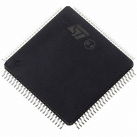
ST10F276Z5T3 STMicroelectronics, ST10F276Z5T3 Datasheet - Page 233

ST10F276Z5T3
Manufacturer Part Number
ST10F276Z5T3
Description
MCU 16BIT 832KBIT FLASH 144-TQFP
Manufacturer
STMicroelectronics
Series
ST10r
Datasheet
1.ST10F276Z5T3.pdf
(239 pages)
Specifications of ST10F276Z5T3
Core Processor
ST10
Core Size
16-Bit
Speed
40MHz
Connectivity
ASC, CAN, EBI/EMI, I²C, SSC, UART/USART
Peripherals
POR, PWM, WDT
Number Of I /o
111
Program Memory Size
832KB (832K x 8)
Program Memory Type
FLASH
Ram Size
68K x 8
Voltage - Supply (vcc/vdd)
4.5 V ~ 5.5 V
Data Converters
A/D 24x10b
Oscillator Type
Internal
Operating Temperature
-40°C ~ 125°C
Package / Case
144-TQFP, 144-VQFP
Cpu Family
ST10
Device Core Size
16b
Frequency (max)
40MHz
Interface Type
CAN/I2C
Total Internal Ram Size
68KB
# I/os (max)
111
Number Of Timers - General Purpose
5
Operating Supply Voltage (typ)
5V
Operating Supply Voltage (max)
5.5V
Operating Supply Voltage (min)
4.5V
On-chip Adc
24-chx10-bit
Instruction Set Architecture
CISC/RISC
Operating Temp Range
-40C to 125C
Operating Temperature Classification
Automotive
Mounting
Surface Mount
Pin Count
144
Package Type
LQFP
Processor Series
ST10F27x
Core
ST10
Data Bus Width
16 bit
Data Ram Size
68 KB
Maximum Clock Frequency
40 MHz
Number Of Programmable I/os
111
Number Of Timers
5
Maximum Operating Temperature
+ 125 C
Mounting Style
SMD/SMT
Minimum Operating Temperature
- 40 C
For Use With
497-6399 - KIT DEV STARTER ST10F276Z5
Lead Free Status / RoHS Status
Lead free / RoHS Compliant
Eeprom Size
-
Lead Free Status / Rohs Status
Compliant
Available stocks
Company
Part Number
Manufacturer
Quantity
Price
Company:
Part Number:
ST10F276Z5T3
Manufacturer:
STMicroelectronics
Quantity:
10 000
ST10F276Z5
24.1.6
However, in certain cases, the PWRDN instruction is not ignored, no further instructions are
fetched from external memory, and the CPU is in a quasi-idle state. This problem only
occurs in the following situations:
1.
2.
Note: The on-chip peripherals, such as the watchdog timer, still operate properly. If the
No problem occurs and the device normally enters Power-down mode if the NMI pin is held
low (PWDCFG = 0) or if all Port 2 pins used to exit from Power-down mode are at inactive
level (PWDCFG = 1).
Workaround
To prevent this problem from occurring, the PWRDN instruction must be preceded by
instructions performing write operations to external memory area or to an XPeripheral.
Otherwise, it is recommended to insert a NOP instruction before PWRDN.
When using a multiplexed bus with memory tri-state wait state, the PWRDN instruction must
be executed from internal RAM or XRAM.
Behavior of CAPCOM outputs in COMPARE mode 3
Description
When a CAPCOM channel is configured in compare mode 3, then the related output level
switches to high when the allocated timer, Tx, matches the related CAPCOM register, CCy.
When an overflow occurs on the CAPCOM timer Tx, it is reloaded with TxREL content and
the output pin is cleared. The output pin level does not change if TxREL and CCy have the
same value.
The related CAPCOM output stays low when the CAPCOM channel is configured in
compare mode 3 and TxREL and Tx related timer registers are loaded with the same value
as CCy. This is obtained by executing the following instructions:
MOV TxREL, #CCy value x =0,1,7,8
MOV Tx, #CCy value x = 0,1,7,8
MOV TxxCON, #data or bfldl/bfldh TxxCON , #mask, #data i.e. an
access is made to the T01CON or T78CON register.
The instructions following the PWRDN instruction are located in an external memory
and a multiplexed bus configuration with memory tri-state waitstate (bit MTTCx = 0) is
used.
The instruction preceding the PWRDN instruction writes to the external memory or to
an XPeripheral (such as XRAM or CAN) and the instructions following the PWRDN
instruction are located in external memory area. In this case, the problem occurs for all
bus configurations.
watchdog timer is not disabled, it resets the device upon an overflow event. However,
interrupts and PEC transfers cannot be processed. Power-down mode is entered if
the NMI signal is asserted low while the device is in this quasi-idle state.
Known limitations
233/239


