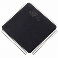
ST10F276Z5T3 STMicroelectronics, ST10F276Z5T3 Datasheet - Page 205

ST10F276Z5T3
Manufacturer Part Number
ST10F276Z5T3
Description
MCU 16BIT 832KBIT FLASH 144-TQFP
Manufacturer
STMicroelectronics
Series
ST10r
Datasheet
1.ST10F276Z5T3.pdf
(239 pages)
Specifications of ST10F276Z5T3
Core Processor
ST10
Core Size
16-Bit
Speed
40MHz
Connectivity
ASC, CAN, EBI/EMI, I²C, SSC, UART/USART
Peripherals
POR, PWM, WDT
Number Of I /o
111
Program Memory Size
832KB (832K x 8)
Program Memory Type
FLASH
Ram Size
68K x 8
Voltage - Supply (vcc/vdd)
4.5 V ~ 5.5 V
Data Converters
A/D 24x10b
Oscillator Type
Internal
Operating Temperature
-40°C ~ 125°C
Package / Case
144-TQFP, 144-VQFP
Cpu Family
ST10
Device Core Size
16b
Frequency (max)
40MHz
Interface Type
CAN/I2C
Total Internal Ram Size
68KB
# I/os (max)
111
Number Of Timers - General Purpose
5
Operating Supply Voltage (typ)
5V
Operating Supply Voltage (max)
5.5V
Operating Supply Voltage (min)
4.5V
On-chip Adc
24-chx10-bit
Instruction Set Architecture
CISC/RISC
Operating Temp Range
-40C to 125C
Operating Temperature Classification
Automotive
Mounting
Surface Mount
Pin Count
144
Package Type
LQFP
Processor Series
ST10F27x
Core
ST10
Data Bus Width
16 bit
Data Ram Size
68 KB
Maximum Clock Frequency
40 MHz
Number Of Programmable I/os
111
Number Of Timers
5
Maximum Operating Temperature
+ 125 C
Mounting Style
SMD/SMT
Minimum Operating Temperature
- 40 C
For Use With
497-6399 - KIT DEV STARTER ST10F276Z5
Lead Free Status / RoHS Status
Lead free / RoHS Compliant
Eeprom Size
-
Lead Free Status / Rohs Status
Compliant
Available stocks
Company
Part Number
Manufacturer
Quantity
Price
Company:
Part Number:
ST10F276Z5T3
Manufacturer:
STMicroelectronics
Quantity:
10 000
ST10F276Z5
23.8.15
Figure 55. 32 kHz crystal oscillator connection diagram
Table 103. Minimum values of negative resistance (module)
The given values of C
printed circuit board: The negative resistance values are calculated assuming additional
5 pF to the values in the table. The crystal shunt capacitance (C
stray capacitance between XTAL3 and XTAL4 pins is globally assumed equal to 4 pF. The
external resistance between XTAL3 and XTAL4 is not necessary, since already present on
the silicon.
External clock drive XTAL1
When Direct Drive configuration is selected during reset, it is possible to drive the CPU clock
directly from the XTAL1 pin, without particular restrictions on the maximum frequency, since
the on-chip oscillator amplifier is bypassed. The speed limit is imposed by internal logic that
targets a maximum CPU frequency of 64 MHz.
In all other clock configurations (Direct Drive with Prescaler or PLL usage) the on-chip
oscillator amplifier is not bypassed, so it determines the input clock speed limit. Then an
external clock source can be used but limited in the range of frequencies defined for the
usage of crystal and resonator (refer also to
External clock drive timing conditions: V
32 kHz
Warning:
C
A
= 6 pF C
-
Direct driving on XTAL3 pin is not supported. Always use a
32 kHz crystal oscillator.
A
do not include the stray capacitance of the package and of the
A
= 12 pF C
-
A
= 15 pF C
-
DD
C
A
ST10F276
= 5 V ±10%, V
Crystal
Table 97 on page
A
= 18 pF C
-
C
A
SS
A
150 kΩ
= 22 pF C
= 0 V, T
198).
0
Electrical characteristics
), the package and the
A
= –40 to +125 °C
A
120 kΩ
= 27 pF C
A
90 kW
= 33 pF
205/239


