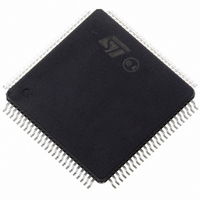
ST10F276Z5T3 STMicroelectronics, ST10F276Z5T3 Datasheet - Page 49

ST10F276Z5T3
Manufacturer Part Number
ST10F276Z5T3
Description
MCU 16BIT 832KBIT FLASH 144-TQFP
Manufacturer
STMicroelectronics
Series
ST10r
Datasheet
1.ST10F276Z5T3.pdf
(239 pages)
Specifications of ST10F276Z5T3
Core Processor
ST10
Core Size
16-Bit
Speed
40MHz
Connectivity
ASC, CAN, EBI/EMI, I²C, SSC, UART/USART
Peripherals
POR, PWM, WDT
Number Of I /o
111
Program Memory Size
832KB (832K x 8)
Program Memory Type
FLASH
Ram Size
68K x 8
Voltage - Supply (vcc/vdd)
4.5 V ~ 5.5 V
Data Converters
A/D 24x10b
Oscillator Type
Internal
Operating Temperature
-40°C ~ 125°C
Package / Case
144-TQFP, 144-VQFP
Cpu Family
ST10
Device Core Size
16b
Frequency (max)
40MHz
Interface Type
CAN/I2C
Total Internal Ram Size
68KB
# I/os (max)
111
Number Of Timers - General Purpose
5
Operating Supply Voltage (typ)
5V
Operating Supply Voltage (max)
5.5V
Operating Supply Voltage (min)
4.5V
On-chip Adc
24-chx10-bit
Instruction Set Architecture
CISC/RISC
Operating Temp Range
-40C to 125C
Operating Temperature Classification
Automotive
Mounting
Surface Mount
Pin Count
144
Package Type
LQFP
Processor Series
ST10F27x
Core
ST10
Data Bus Width
16 bit
Data Ram Size
68 KB
Maximum Clock Frequency
40 MHz
Number Of Programmable I/os
111
Number Of Timers
5
Maximum Operating Temperature
+ 125 C
Mounting Style
SMD/SMT
Minimum Operating Temperature
- 40 C
For Use With
497-6399 - KIT DEV STARTER ST10F276Z5
Lead Free Status / RoHS Status
Lead free / RoHS Compliant
Eeprom Size
-
Lead Free Status / Rohs Status
Compliant
Available stocks
Company
Part Number
Manufacturer
Quantity
Price
Company:
Part Number:
ST10F276Z5T3
Manufacturer:
STMicroelectronics
Quantity:
10 000
ST10F276Z5
5.2.2
Valid dominant bit on CAN1 RxD
The ST10F276Z5 starts bootstrapping via CAN1; the bootstrapping method is new and is
described in the next paragraph 5.4.
loader. It clearly illustrates how the new functionalities are implemented:
●
●
ST10 configuration in BSL
When the ST10F276Z5 has entered BSL mode, the configuration shown in
automatically set (values that deviate from the normal reset values are marked in bold).
Table 30.
1. In Bootstrap modes (standard or alternate) ROMEN, bit 10 of SYSCON, is always set regardless of EA pin
2. BUSCON0 is initialized with 0000h, external bus disabled, if pin EA is high during reset. If pin EA is low
Watchdog Timer
Register SYSCON
Context Pointer CP
Register STKUN
Stack Pointer SP
Register STKOV
Register BUSCON0
Register S0CON
Register S0BG
P3.10 / TXD0
DP3.10
CAN1 Status/Control
Register
CAN1 Bit Timing Register
XPERCON
P4.6 / CAN1_TxD
DP4.6
Function or register
level. BYTDIS, bit 9 of SYSCON, is set according to data bus width selection via Port0 configuration.
during reset, BUSACT0, bit 10, and ALECTL0, bit 9, are set enabling the external bus with lengthened ALE
signal. BTYP field, bit 7 and 6, is set according to Port0 configuration.
UART: UART has priority over CAN after a falling edge on CAN1_RxD until the first
valid rising edge on CAN1_RxD;
CAN: Pulses on CAN1_RxD shorter than 20*CPU-cycles are filtered.
ST10 configuration in BSL mode
access to ‘0’ frame
access to ‘00’ byte
access to startup
configuration
0404
Disabled
Access
FC00
FA00
FA40
FA00
042D
8011
0000
‘1’
‘1’
‘1’
‘1’
Figure 5
H
H
H
H
H
H
H
H
(1)
(2)
shows the program flow of the new bootstrap
Initialized only if Bootstrap via CAN
XPEN bit set for Bootstrap via CAN or
Alternate Boot mode
Initialized only if Bootstrap via UART
Initialized only if Bootstrap via UART
Initialized only if Bootstrap via UART
Initialized only if Bootstrap via UART
Initialized only if Bootstrap via CAN
XRAM1-2, XFlash, CAN1 and XMISC
enabled. Initialized only if Bootstrap via CAN
Initialized only if Bootstrap via CAN
Initialized only if Bootstrap via CAN
Notes
Bootstrap loader
Table 30
is
49/239


