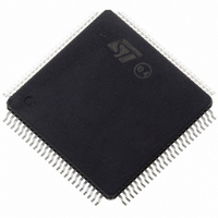
ST10F276Z5T3 STMicroelectronics, ST10F276Z5T3 Datasheet - Page 179

ST10F276Z5T3
Manufacturer Part Number
ST10F276Z5T3
Description
MCU 16BIT 832KBIT FLASH 144-TQFP
Manufacturer
STMicroelectronics
Series
ST10r
Datasheet
1.ST10F276Z5T3.pdf
(239 pages)
Specifications of ST10F276Z5T3
Core Processor
ST10
Core Size
16-Bit
Speed
40MHz
Connectivity
ASC, CAN, EBI/EMI, I²C, SSC, UART/USART
Peripherals
POR, PWM, WDT
Number Of I /o
111
Program Memory Size
832KB (832K x 8)
Program Memory Type
FLASH
Ram Size
68K x 8
Voltage - Supply (vcc/vdd)
4.5 V ~ 5.5 V
Data Converters
A/D 24x10b
Oscillator Type
Internal
Operating Temperature
-40°C ~ 125°C
Package / Case
144-TQFP, 144-VQFP
Cpu Family
ST10
Device Core Size
16b
Frequency (max)
40MHz
Interface Type
CAN/I2C
Total Internal Ram Size
68KB
# I/os (max)
111
Number Of Timers - General Purpose
5
Operating Supply Voltage (typ)
5V
Operating Supply Voltage (max)
5.5V
Operating Supply Voltage (min)
4.5V
On-chip Adc
24-chx10-bit
Instruction Set Architecture
CISC/RISC
Operating Temp Range
-40C to 125C
Operating Temperature Classification
Automotive
Mounting
Surface Mount
Pin Count
144
Package Type
LQFP
Processor Series
ST10F27x
Core
ST10
Data Bus Width
16 bit
Data Ram Size
68 KB
Maximum Clock Frequency
40 MHz
Number Of Programmable I/os
111
Number Of Timers
5
Maximum Operating Temperature
+ 125 C
Mounting Style
SMD/SMT
Minimum Operating Temperature
- 40 C
For Use With
497-6399 - KIT DEV STARTER ST10F276Z5
Lead Free Status / RoHS Status
Lead free / RoHS Compliant
Eeprom Size
-
Lead Free Status / Rohs Status
Compliant
Available stocks
Company
Part Number
Manufacturer
Quantity
Price
Company:
Part Number:
ST10F276Z5T3
Manufacturer:
STMicroelectronics
Quantity:
10 000
ST10F276Z5
23.3
Power considerations
The average chip-junction temperature, T
following equation:
Where:
T
Θ
P
P
P
Most often in applications, P
significant if the device is configured to continuously drive external modules and/or
memories.
An approximate relationship between P
Therefore (solving equations 1 and 2):
Where:
K is a constant for the particular part, which may be determined from equation (3) by
measuring P
are obtained by solving equations (1) and (2) iteratively for any value of T
Table 90.
Based on thermal characteristics of the package and with reference to the power
consumption figures provided in the next tables and diagrams, the following product
classification can be proposed. In any case, the exact power consumption of the device
inside the application must be computed according to different working conditions, thermal
profiles, real thermal resistance of the system (including printed circuit board or other
substrata) and I/O activity.
A
D
INT
I/O
JA
Symbol
is the Ambient Temperature in °C,
is the sum of P
is the Package Junction-to-Ambient Thermal Resistance, in °C/W,
represents the Power Dissipation on Input and Output Pins; user determined.
Θ
is the product of I
JA
D
Thermal characteristics
Thermal resistance junction-ambient
PQFP 144 - 28 x 28 x 3.4 mm / 0.65 mm pitch
LQFP 144 - 20 x 20 mm / 0.5 mm pitch
LQFP 144 - 20 x 20 mm / 0.5 mm pitch on four layer
FR4 board (2 layers signals / 2 layers power)
(at equilibrium) for a known T
INT
and P
DD
and V
K = P
I/O
I/O
< P
(P
DD
D
Description
P
D
x (T
T
, expressed in Watt. This is the Chip Internal Power,
INT
D
J
= P
= K / (T
= T
,which may be ignored. On the other hand, P
A
INT
+ 273 °C) + Θ
D
A
and T
J
+ (P
+ P
, in degrees Celsius, is calculated using the
A.
J
+ 273 °C) (2)
I/O
D
Using this value of K, the values of P
J
x Θ
),
(if P
JA
I/O
JA
) 1)
x P
is neglected) is given by:
D
2
(3)
Value (typical)
Electrical characteristics
30
40
35
A
.
I/O
D
°C/W
may be
Unit
179/239
and T
J


