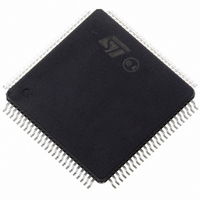
ST10F276Z5T3 STMicroelectronics, ST10F276Z5T3 Datasheet - Page 186

ST10F276Z5T3
Manufacturer Part Number
ST10F276Z5T3
Description
MCU 16BIT 832KBIT FLASH 144-TQFP
Manufacturer
STMicroelectronics
Series
ST10r
Datasheet
1.ST10F276Z5T3.pdf
(239 pages)
Specifications of ST10F276Z5T3
Core Processor
ST10
Core Size
16-Bit
Speed
40MHz
Connectivity
ASC, CAN, EBI/EMI, I²C, SSC, UART/USART
Peripherals
POR, PWM, WDT
Number Of I /o
111
Program Memory Size
832KB (832K x 8)
Program Memory Type
FLASH
Ram Size
68K x 8
Voltage - Supply (vcc/vdd)
4.5 V ~ 5.5 V
Data Converters
A/D 24x10b
Oscillator Type
Internal
Operating Temperature
-40°C ~ 125°C
Package / Case
144-TQFP, 144-VQFP
Cpu Family
ST10
Device Core Size
16b
Frequency (max)
40MHz
Interface Type
CAN/I2C
Total Internal Ram Size
68KB
# I/os (max)
111
Number Of Timers - General Purpose
5
Operating Supply Voltage (typ)
5V
Operating Supply Voltage (max)
5.5V
Operating Supply Voltage (min)
4.5V
On-chip Adc
24-chx10-bit
Instruction Set Architecture
CISC/RISC
Operating Temp Range
-40C to 125C
Operating Temperature Classification
Automotive
Mounting
Surface Mount
Pin Count
144
Package Type
LQFP
Processor Series
ST10F27x
Core
ST10
Data Bus Width
16 bit
Data Ram Size
68 KB
Maximum Clock Frequency
40 MHz
Number Of Programmable I/os
111
Number Of Timers
5
Maximum Operating Temperature
+ 125 C
Mounting Style
SMD/SMT
Minimum Operating Temperature
- 40 C
For Use With
497-6399 - KIT DEV STARTER ST10F276Z5
Lead Free Status / RoHS Status
Lead free / RoHS Compliant
Eeprom Size
-
Lead Free Status / Rohs Status
Compliant
Available stocks
Company
Part Number
Manufacturer
Quantity
Price
Company:
Part Number:
ST10F276Z5T3
Manufacturer:
STMicroelectronics
Quantity:
10 000
Electrical characteristics
186/239
Table 93.
1. The figures are given after about 100 cycles due to testing routines (0 cycles at the final customer).
2. Word and Double Word Programming times are provided as average value derived from a full sector
3. Bank Erase is obtained through a multiple Sector Erase operation (setting bits related to all sectors of the
4. Module Erase is obtained through a sequence of two Bank Erase operations (since each module is
5. Chip Erase is obtained through a sequence of two Module Erase operations on I- and X-Module.
6. Not 100% tested, guaranteed by design characterization
Table 94.
1. Two 64 Kbyte Flash Sectors may be typically used to emulate up to 4, 8 or 16 Kbytes of EEPROM.
Erase suspend latency
Erase suspend request
Rate
Set protection
.
Number of program / erase
programming time: Absolute value of a Word or Double Word Programming time could be longer than the
provided average value.
Bank).
composed by two Banks).
Therefore, in case of an emulation of a 16 Kbyte EEPROM, 100000 Flash Program / Erase cycles are
equivalent to 800000 EEPROM Program/Erase cycles.
For an efficient use of the Read While Write feature and/or EEPROM Emulation please refer to dedicated
Application Note document (AN2061 - EEPROM Emulation with ST10F2xx). Contact your local field
service, local sales person or STMicroelectronics representative to obtain a copy of such a guideline
document.
(-40 °C ≤ T
(6)
Parameter
100000
cycles
0 - 100
10000
Flash characteristics (continued)
Data retention characteristics
1000
(6)
A
≤ 125 °C)
(6)
0 cycles
T
A
Typical
= 25 °C
20
40
–
(1)
0 cycles
(code store)
832 Kbyte
> 20 years
170
(average ambient temperature 60 °C)
30
20
-
-
-
T
Maximum
A
(1)
= 125 °C
Data retention time
100k cycles
170
30
20
(EEPROM emulation)
Unit
ms
µs
µs
> 20 years
> 20 years
64 Kbyte
10 years
Min delay between
two requests
1 year
ST10F276Z5
Notes
(1)


