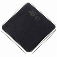
ST10F276Z5T3 STMicroelectronics, ST10F276Z5T3 Datasheet - Page 178

ST10F276Z5T3
Manufacturer Part Number
ST10F276Z5T3
Description
MCU 16BIT 832KBIT FLASH 144-TQFP
Manufacturer
STMicroelectronics
Series
ST10r
Datasheet
1.ST10F276Z5T3.pdf
(239 pages)
Specifications of ST10F276Z5T3
Core Processor
ST10
Core Size
16-Bit
Speed
40MHz
Connectivity
ASC, CAN, EBI/EMI, I²C, SSC, UART/USART
Peripherals
POR, PWM, WDT
Number Of I /o
111
Program Memory Size
832KB (832K x 8)
Program Memory Type
FLASH
Ram Size
68K x 8
Voltage - Supply (vcc/vdd)
4.5 V ~ 5.5 V
Data Converters
A/D 24x10b
Oscillator Type
Internal
Operating Temperature
-40°C ~ 125°C
Package / Case
144-TQFP, 144-VQFP
Cpu Family
ST10
Device Core Size
16b
Frequency (max)
40MHz
Interface Type
CAN/I2C
Total Internal Ram Size
68KB
# I/os (max)
111
Number Of Timers - General Purpose
5
Operating Supply Voltage (typ)
5V
Operating Supply Voltage (max)
5.5V
Operating Supply Voltage (min)
4.5V
On-chip Adc
24-chx10-bit
Instruction Set Architecture
CISC/RISC
Operating Temp Range
-40C to 125C
Operating Temperature Classification
Automotive
Mounting
Surface Mount
Pin Count
144
Package Type
LQFP
Processor Series
ST10F27x
Core
ST10
Data Bus Width
16 bit
Data Ram Size
68 KB
Maximum Clock Frequency
40 MHz
Number Of Programmable I/os
111
Number Of Timers
5
Maximum Operating Temperature
+ 125 C
Mounting Style
SMD/SMT
Minimum Operating Temperature
- 40 C
For Use With
497-6399 - KIT DEV STARTER ST10F276Z5
Lead Free Status / RoHS Status
Lead free / RoHS Compliant
Eeprom Size
-
Lead Free Status / Rohs Status
Compliant
Available stocks
Company
Part Number
Manufacturer
Quantity
Price
Company:
Part Number:
ST10F276Z5T3
Manufacturer:
STMicroelectronics
Quantity:
10 000
Electrical characteristics
23
23.1
23.2
178/239
Electrical characteristics
Absolute maximum ratings
Stresses above those listed under “Absolute Maximum Ratings” may cause permanent
damage to the device. This is a stress rating only and functional operation of the device at
these or any other conditions above those indicated in the operational sections of this
specification is not implied. Exposure to absolute maximum rating conditions for extended
periods may affect device reliability. During overload conditions (V
voltage on pins with respect to ground (V
absolute maximum ratings.
During Power-on and Power-off transients (including Standby entering/exiting phases), the
relationships between voltages applied to the device and the main V
respected. In particular, power-on and power-off of V
transient, in order to avoid undesired current injection through the on-chip protection diodes.
Table 88.
Recommended operating conditions
Table 89.
1. The value of the V
2. For details on operating conditions concerning the usage of A/D converter, refer to
Symbol
V
Symbol
V
V
ESD
I
V
V
V
exceed the upper limit (up to 6.0 V) for a maximum of 100 hrs over the global 300000 hrs, representing the
lifetime of the device (about 30 years). On the other hand, it is possible to exceed the lower limit (down to
4.0 V) whenever RTC and 32 kHz on-chip oscillator amplifier are turned off (only Standby RAM powered
through V
V
1 mA).
AGND
T
AREF
V
STBY
I
TOV
OV
V
DD
ST
STBY
AREF
STBY
IO
T
T
DD
A
J
/EA pin can generate a spurious static consumption on V
Voltage on V
Voltage on V
Voltage on V
Voltage on V
Voltage on any pin with respect to ground (V
Input current on any pin during overload condition
Absolute sum of all input currents during overload condition
Storage temperature
ESD susceptibility (human body model)
STBY
Operating supply voltage
Operating standby supply voltage
Operating analog reference voltage
Ambient temperature under bias
Junction temperature under bias
Absolute maximum ratings
Recommended operating conditions
pin in Standby mode). When V
STBY
DD
STBY
AREF
AGND
voltage is specified in the range 4.5 - 5.5 V. Nevertheless, it is acceptable to
pins with respect to ground (V
pin with respect to ground (V
pin with respect to ground (V
pin with respect to ground (V
Parameter
Parameter
STBY
(1)
SS
(2)
) must not exceed the values defined by the
voltage is lower than main V
SS
SS
SS
)
SS
SS
)
)
)
)
AREF
DD
power supply (in the range of tenth of
must be coherent with the V
Min.
–40
4.5
0
IN
DD
- 0.3 to V
- 0.5 to V
> V
DD
, the input section of
- 0.3 to +6.5
- 65 to +150
Section
DD
must always be
Value
2000
| 75 |
± 10
V
Max.
+125
+150
SS
V
5.5
or V
DD
DD
DD
23.7.
+ 0.3
+ 0.5
ST10F276Z5
IN
< V
SS
Unit
°C
V
Unit
DD
mA
) the
°C
V
V


