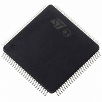
ST10F276Z5T3 STMicroelectronics, ST10F276Z5T3 Datasheet - Page 114

ST10F276Z5T3
Manufacturer Part Number
ST10F276Z5T3
Description
MCU 16BIT 832KBIT FLASH 144-TQFP
Manufacturer
STMicroelectronics
Series
ST10r
Datasheet
1.ST10F276Z5T3.pdf
(239 pages)
Specifications of ST10F276Z5T3
Core Processor
ST10
Core Size
16-Bit
Speed
40MHz
Connectivity
ASC, CAN, EBI/EMI, I²C, SSC, UART/USART
Peripherals
POR, PWM, WDT
Number Of I /o
111
Program Memory Size
832KB (832K x 8)
Program Memory Type
FLASH
Ram Size
68K x 8
Voltage - Supply (vcc/vdd)
4.5 V ~ 5.5 V
Data Converters
A/D 24x10b
Oscillator Type
Internal
Operating Temperature
-40°C ~ 125°C
Package / Case
144-TQFP, 144-VQFP
Cpu Family
ST10
Device Core Size
16b
Frequency (max)
40MHz
Interface Type
CAN/I2C
Total Internal Ram Size
68KB
# I/os (max)
111
Number Of Timers - General Purpose
5
Operating Supply Voltage (typ)
5V
Operating Supply Voltage (max)
5.5V
Operating Supply Voltage (min)
4.5V
On-chip Adc
24-chx10-bit
Instruction Set Architecture
CISC/RISC
Operating Temp Range
-40C to 125C
Operating Temperature Classification
Automotive
Mounting
Surface Mount
Pin Count
144
Package Type
LQFP
Processor Series
ST10F27x
Core
ST10
Data Bus Width
16 bit
Data Ram Size
68 KB
Maximum Clock Frequency
40 MHz
Number Of Programmable I/os
111
Number Of Timers
5
Maximum Operating Temperature
+ 125 C
Mounting Style
SMD/SMT
Minimum Operating Temperature
- 40 C
For Use With
497-6399 - KIT DEV STARTER ST10F276Z5
Lead Free Status / RoHS Status
Lead free / RoHS Compliant
Eeprom Size
-
Lead Free Status / Rohs Status
Compliant
Available stocks
Company
Part Number
Manufacturer
Quantity
Price
Company:
Part Number:
ST10F276Z5T3
Manufacturer:
STMicroelectronics
Quantity:
10 000
System reset
114/239
always with FFFFh, which leads to an illegal opcode and consequently a trap event is
generated.
Exit from synchronous reset state
The reset sequence is extended until RSTIN level becomes high. Besides, it is internally
prolonged by the FLASH initialization when EA=1 (internal memory selected). Then, the
code execution restarts. The system configuration is latched from Port0, and ALE, RD and
WR/WRL pins are driven to their inactive level. The device starts program execution from
memory location 00'0000h in code segment 0. This starting location will typically point to the
general initialization routine. Timing of synchronous reset sequence are summarized in
Figures 28 and 29 where a Short Reset event is shown, with particular highlighting on the
fact that it can degenerate into Long Reset: the two figures show the behavior when booting
from internal or external memory respectively.
a typical synchronous Long Reset, again when booting from internal or external memory.
Synchronous reset and RPD pin
Whenever the RSTIN pin is pulled low (by external hardware or as a consequence of a
Bidirectional reset), the RPD internal weak pull-down is activated. The external capacitance
(if any) on RPD pin is slowly discharged through the internal weak pull-down. If the voltage
level on RPD pin reaches the input low threshold (around 2.5 V), the reset event becomes
immediately asynchronous. In case of hardware reset (short or long) the situation goes
immediately to the one illustrated in
the input threshold: the asynchronous reset is completed coherently. To grant the normal
completion of a synchronous reset, the value of the capacitance shall be big enough to
maintain the voltage on RPD pin sufficient high along the duration of the internal reset
sequence.
For a Software or Watchdog reset events, an active synchronous reset is completed
regardless of the RPD status.
It is important to highlight that the signal that makes RPD status transparent under reset is
the internal RSTF (after the noise filter).
Figure
26. There is no effect if RPD comes again above
Figure 30
and
Figure 31
reports the timing of
ST10F276Z5


