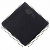
ST10F276Z5T3 STMicroelectronics, ST10F276Z5T3 Datasheet - Page 229

ST10F276Z5T3
Manufacturer Part Number
ST10F276Z5T3
Description
MCU 16BIT 832KBIT FLASH 144-TQFP
Manufacturer
STMicroelectronics
Series
ST10r
Datasheet
1.ST10F276Z5T3.pdf
(239 pages)
Specifications of ST10F276Z5T3
Core Processor
ST10
Core Size
16-Bit
Speed
40MHz
Connectivity
ASC, CAN, EBI/EMI, I²C, SSC, UART/USART
Peripherals
POR, PWM, WDT
Number Of I /o
111
Program Memory Size
832KB (832K x 8)
Program Memory Type
FLASH
Ram Size
68K x 8
Voltage - Supply (vcc/vdd)
4.5 V ~ 5.5 V
Data Converters
A/D 24x10b
Oscillator Type
Internal
Operating Temperature
-40°C ~ 125°C
Package / Case
144-TQFP, 144-VQFP
Cpu Family
ST10
Device Core Size
16b
Frequency (max)
40MHz
Interface Type
CAN/I2C
Total Internal Ram Size
68KB
# I/os (max)
111
Number Of Timers - General Purpose
5
Operating Supply Voltage (typ)
5V
Operating Supply Voltage (max)
5.5V
Operating Supply Voltage (min)
4.5V
On-chip Adc
24-chx10-bit
Instruction Set Architecture
CISC/RISC
Operating Temp Range
-40C to 125C
Operating Temperature Classification
Automotive
Mounting
Surface Mount
Pin Count
144
Package Type
LQFP
Processor Series
ST10F27x
Core
ST10
Data Bus Width
16 bit
Data Ram Size
68 KB
Maximum Clock Frequency
40 MHz
Number Of Programmable I/os
111
Number Of Timers
5
Maximum Operating Temperature
+ 125 C
Mounting Style
SMD/SMT
Minimum Operating Temperature
- 40 C
For Use With
497-6399 - KIT DEV STARTER ST10F276Z5
Lead Free Status / RoHS Status
Lead free / RoHS Compliant
Eeprom Size
-
Lead Free Status / Rohs Status
Compliant
Available stocks
Company
Part Number
Manufacturer
Quantity
Price
Company:
Part Number:
ST10F276Z5T3
Manufacturer:
STMicroelectronics
Quantity:
10 000
ST10F276Z5
Therefore, to prevent the locking situation from occurring, it is important to make sure that
no task can disable interrupts for a period of time during which 2 injection requests can
occur before a read operation is performed.
Detailed analysis
Channel Injection mode allows to convert a specific analog channel without changing the
current operating mode. It can also be used when the A/D converter is running in continuous
or auto scan mode.
The following main points need to be highlighted:
●
●
●
If the temporary data register used for ADDAT2 read mode is full and a new injection request
occurs, then the new converted value is stored into a temporary data register until the
previous one is read from ADDAT2 register.
To ensure correct operation as soon as ADDAT2 register is read, the last converted value
should be moved from temporary register to ADDAT2 and the ADEINT interrupt should be
generated.
In real circumstances, as soon as the ADDAT2 register is read, the last converted value is
correctly moved from the temporary register to the ADDAT2, but no ADEINT interrupt
request is sent to the Interrupt controller (see
does not know that a new converted value is available in the ADDAT2 register. When the
next injection request is issued, the A/D converter fills the temporary register again without
generating any ADEINT interrupt request and the converter is stalled. The A/D converter
stays in the “wait for read ADDAT2 register” condition forever.
The A/D converter must be in Wait for ADDAT read mode in order for the Channel
Injection mode to operate properly.
At the end of the injected conversion the data is available in the alternate result register,
ADDAT2, and a Channel Injection Complete Interrupt request is generated (ADEIR
Flag).
If the temporary data register used for ADDAT2 read mode is full, the next conversion
(standard or injected) is suspended. The temporary register then stores the content of
ADDAT (standard conversion) or ADDAT2 (injected conversion).
This allows the CPU to read the last converted value (see
Figure
71). As a consequence the CPU/PEC
Figure
Known limitations
70).
229/239


