HD64F7051SFJ20V Renesas Electronics America, HD64F7051SFJ20V Datasheet - Page 20
HD64F7051SFJ20V
Manufacturer Part Number
HD64F7051SFJ20V
Description
MCU 5V 256K J-TEMP PB-FREE QFP-1
Manufacturer
Renesas Electronics America
Series
SuperH® SH7050r
Datasheet
1.HD64F7050SFJ20V.pdf
(843 pages)
Specifications of HD64F7051SFJ20V
Core Processor
SH-2
Core Size
32-Bit
Speed
20MHz
Connectivity
EBI/EMI, SCI
Peripherals
DMA, WDT
Number Of I /o
102
Program Memory Size
256KB (256K x 8)
Program Memory Type
FLASH
Ram Size
10K x 8
Voltage - Supply (vcc/vdd)
4.5 V ~ 5.5 V
Data Converters
A/D 16x10b
Oscillator Type
Internal
Operating Temperature
-40°C ~ 85°C
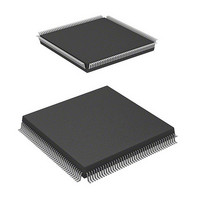
Package / Case
168-QFP
Lead Free Status / RoHS Status
Lead free / RoHS Compliant
Eeprom Size
-
Available stocks
Company
Part Number
Manufacturer
Quantity
Price
Company:

Part Number:
HD64F7051SFJ20V
Manufacturer:
RENESAS
Quantity:
101
Part Number:
HD64F7051SFJ20V
Manufacturer:
RENESAS/瑞萨
Quantity:
20 000


19.3 Pin Configuration.............................................................................................................. 593
19.4 Register Configuration...................................................................................................... 594
19.5 Register Descriptions ........................................................................................................ 595
19.6 On-Board Programming Modes........................................................................................ 604
19.7 Programming/Erasing Flash Memory ............................................................................... 610
19.8 Protection .......................................................................................................................... 615
19.9 Flash Memory Emulation in RAM ................................................................................... 619
19.10 Note on Flash Memory Programming/Erasing ................................................................. 621
19.11 Flash Memory Programmer Mode .................................................................................... 621
19.12 Notes when Converting the F-ZTAT Application Software to the Mask-ROM
Rev. 5.00 Jan 06, 2006 page xviii of xx
19.2.4 Flash Memory Emulation in RAM ...................................................................... 590
19.2.5 Differences between Boot Mode and User Program Mode ................................. 591
19.2.6 Block Configuration ............................................................................................ 592
19.5.1 Flash Memory Control Register 1 (FLMCR1)..................................................... 595
19.5.2 Flash Memory Control Register 2 (FLMCR2)..................................................... 598
19.5.3 Erase Block Register 1 (EBR1) ........................................................................... 601
19.5.4 Erase Block Register 2 (EBR2) ........................................................................... 602
19.5.5 RAM Emulation Register (RAMER)................................................................... 603
19.6.1 Boot Mode ........................................................................................................... 605
19.6.2 User Program Mode............................................................................................. 609
19.7.1 Program Mode (n = 1 for Addresses H'0000 to H'1FFFF,
19.7.2 Program-Verify Mode (n = 1 for Addresses H'0000 to H'1FFFF,
19.7.3 Erase Mode (n = 1 for Addresses H'0000 to H'1FFFF,
19.7.4 Erase-Verify Mode (n = 1 for Addresses H'0000 to H'1FFFF,
19.8.1 Hardware Protection ............................................................................................ 615
19.8.2 Software Protection.............................................................................................. 616
19.8.3 Error Protection.................................................................................................... 617
19.11.1 Socket Adapter Pin Correspondence Diagram..................................................... 622
19.11.2 Programmer Mode Operation .............................................................................. 624
19.11.3 Memory Read Mode ............................................................................................ 625
19.11.4 Auto-Program Mode ............................................................................................ 629
19.11.5 Auto-Erase Mode................................................................................................. 631
19.11.6 Status Read Mode ................................................................................................ 633
19.11.7 Status Polling ....................................................................................................... 635
19.11.8 Programmer Mode Transition Time .................................................................... 636
19.11.9 Cautions Concerning Memory Programming ...................................................... 637
Versions ............................................................................................................................ 637
n = 2 for Addresses H'20000 to H'3FFFF) ........................................................... 610
n = 2 for Addresses H'20000 to H'3FFFF) ........................................................... 611
n = 2 for Addresses H'20000 to H'3FFFF) ........................................................... 613
n = 2 for Addresses H'20000 to H'3FFFF) ........................................................... 613
Related parts for HD64F7051SFJ20V
Image
Part Number
Description
Manufacturer
Datasheet
Request
R

Part Number:
Description:
KIT STARTER FOR M16C/29
Manufacturer:
Renesas Electronics America
Datasheet:

Part Number:
Description:
KIT STARTER FOR R8C/2D
Manufacturer:
Renesas Electronics America
Datasheet:

Part Number:
Description:
R0K33062P STARTER KIT
Manufacturer:
Renesas Electronics America
Datasheet:

Part Number:
Description:
KIT STARTER FOR R8C/23 E8A
Manufacturer:
Renesas Electronics America
Datasheet:

Part Number:
Description:
KIT STARTER FOR R8C/25
Manufacturer:
Renesas Electronics America
Datasheet:

Part Number:
Description:
KIT STARTER H8S2456 SHARPE DSPLY
Manufacturer:
Renesas Electronics America
Datasheet:

Part Number:
Description:
KIT STARTER FOR R8C38C
Manufacturer:
Renesas Electronics America
Datasheet:

Part Number:
Description:
KIT STARTER FOR R8C35C
Manufacturer:
Renesas Electronics America
Datasheet:

Part Number:
Description:
KIT STARTER FOR R8CL3AC+LCD APPS
Manufacturer:
Renesas Electronics America
Datasheet:
Part Number:
Description:
KIT STARTER FOR RX610
Manufacturer:
Renesas Electronics America
Datasheet:

Part Number:
Description:
KIT STARTER FOR R32C/118
Manufacturer:
Renesas Electronics America
Datasheet:

Part Number:
Description:
KIT DEV RSK-R8C/26-29
Manufacturer:
Renesas Electronics America
Datasheet:

Part Number:
Description:
KIT STARTER FOR SH7124
Manufacturer:
Renesas Electronics America
Datasheet:

Part Number:
Description:
KIT STARTER FOR H8SX/1622
Manufacturer:
Renesas Electronics America
Datasheet:

Part Number:
Description:
KIT DEV FOR SH7203
Manufacturer:
Renesas Electronics America
Datasheet: