HD64F7051SFJ20V Renesas Electronics America, HD64F7051SFJ20V Datasheet - Page 9
HD64F7051SFJ20V
Manufacturer Part Number
HD64F7051SFJ20V
Description
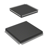
MCU 5V 256K J-TEMP PB-FREE QFP-1
Manufacturer
Renesas Electronics America
Series
SuperH® SH7050r
Datasheet
1.HD64F7050SFJ20V.pdf
(843 pages)
Specifications of HD64F7051SFJ20V
Core Processor
SH-2
Core Size
32-Bit
Speed
20MHz
Connectivity
EBI/EMI, SCI
Peripherals
DMA, WDT
Number Of I /o
102
Program Memory Size
256KB (256K x 8)
Program Memory Type
FLASH
Ram Size
10K x 8
Voltage - Supply (vcc/vdd)
4.5 V ~ 5.5 V
Data Converters
A/D 16x10b
Oscillator Type
Internal
Operating Temperature
-40°C ~ 85°C
Package / Case
168-QFP
Lead Free Status / RoHS Status
Lead free / RoHS Compliant
Eeprom Size
-
Available stocks
Company
Part Number
Manufacturer
Quantity
Price
Company:

Part Number:
HD64F7051SFJ20V
Manufacturer:
RENESAS
Quantity:
101
Part Number:
HD64F7051SFJ20V
Manufacturer:
RENESAS/瑞萨
Quantity:
20 000


Section 1 Overview
1.1
1.2
1.3
Section 2 CPU
2.1
2.2
2.3
2.4
2.5
Section 3 Operating Modes
3.1
Section 4 Clock Pulse Generator (CPG)
4.1
4.2
4.3
Features .............................................................................................................................
Block Diagram ..................................................................................................................
Pin Arrangement and Pin Functions .................................................................................
1.3.1
1.3.2
1.3.3
Register Configuration...................................................................................................... 21
2.1.1
2.1.2
2.1.3
2.1.4
Data Formats..................................................................................................................... 24
2.2.1
2.2.2
2.2.3
Instruction Features........................................................................................................... 25
2.3.1
2.3.2
2.3.3
Instruction Set by Classification ....................................................................................... 36
Processing States............................................................................................................... 48
2.5.1
Operating Mode Selection ................................................................................................ 51
Overview........................................................................................................................... 53
4.1.1
4.1.2
Clock Operating Modes .................................................................................................... 55
Clock Source..................................................................................................................... 56
4.3.1
4.3.2
Pin Arrangement ..................................................................................................
Pin Functions .......................................................................................................
Pin Assignments................................................................................................... 15
General Registers (Rn)......................................................................................... 21
Control Registers ................................................................................................. 22
System Registers.................................................................................................. 23
Initial Values of Registers.................................................................................... 23
Data Format in Registers...................................................................................... 24
Data Format in Memory....................................................................................... 24
Immediate Data Format ....................................................................................... 25
RISC-Type Instruction Set................................................................................... 25
Addressing Modes ............................................................................................... 29
Instruction Format................................................................................................ 33
State Transitions................................................................................................... 48
Block Diagram ..................................................................................................... 54
Pin Configuration................................................................................................. 55
Connecting a Crystal Oscillator ........................................................................... 56
External Clock Input Method............................................................................... 57
...................................................................................................................... 21
.............................................................................................................
............................................................................................... 51
Contents
....................................................................... 53
Rev. 5.00 Jan 06, 2006 page vii of xx
1
1
7
8
8
9
Related parts for HD64F7051SFJ20V
Image
Part Number
Description
Manufacturer
Datasheet
Request
R

Part Number:
Description:
KIT STARTER FOR M16C/29
Manufacturer:
Renesas Electronics America
Datasheet:

Part Number:
Description:
KIT STARTER FOR R8C/2D
Manufacturer:
Renesas Electronics America
Datasheet:

Part Number:
Description:
R0K33062P STARTER KIT
Manufacturer:
Renesas Electronics America
Datasheet:

Part Number:
Description:
KIT STARTER FOR R8C/23 E8A
Manufacturer:
Renesas Electronics America
Datasheet:

Part Number:
Description:
KIT STARTER FOR R8C/25
Manufacturer:
Renesas Electronics America
Datasheet:

Part Number:
Description:
KIT STARTER H8S2456 SHARPE DSPLY
Manufacturer:
Renesas Electronics America
Datasheet:

Part Number:
Description:
KIT STARTER FOR R8C38C
Manufacturer:
Renesas Electronics America
Datasheet:

Part Number:
Description:
KIT STARTER FOR R8C35C
Manufacturer:
Renesas Electronics America
Datasheet:

Part Number:
Description:
KIT STARTER FOR R8CL3AC+LCD APPS
Manufacturer:
Renesas Electronics America
Datasheet:
Part Number:
Description:
KIT STARTER FOR RX610
Manufacturer:
Renesas Electronics America
Datasheet:

Part Number:
Description:
KIT STARTER FOR R32C/118
Manufacturer:
Renesas Electronics America
Datasheet:

Part Number:
Description:
KIT DEV RSK-R8C/26-29
Manufacturer:
Renesas Electronics America
Datasheet:

Part Number:
Description:
KIT STARTER FOR SH7124
Manufacturer:
Renesas Electronics America
Datasheet:

Part Number:
Description:
KIT STARTER FOR H8SX/1622
Manufacturer:
Renesas Electronics America
Datasheet:

Part Number:
Description:
KIT DEV FOR SH7203
Manufacturer:
Renesas Electronics America
Datasheet: