HD64F7051SFJ20V Renesas Electronics America, HD64F7051SFJ20V Datasheet - Page 465
HD64F7051SFJ20V
Manufacturer Part Number
HD64F7051SFJ20V
Description
MCU 5V 256K J-TEMP PB-FREE QFP-1
Manufacturer
Renesas Electronics America
Series
SuperH® SH7050r
Datasheet
1.HD64F7050SFJ20V.pdf
(843 pages)
Specifications of HD64F7051SFJ20V
Core Processor
SH-2
Core Size
32-Bit
Speed
20MHz
Connectivity
EBI/EMI, SCI
Peripherals
DMA, WDT
Number Of I /o
102
Program Memory Size
256KB (256K x 8)
Program Memory Type
FLASH
Ram Size
10K x 8
Voltage - Supply (vcc/vdd)
4.5 V ~ 5.5 V
Data Converters
A/D 16x10b
Oscillator Type
Internal
Operating Temperature
-40°C ~ 85°C
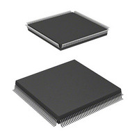
Package / Case
168-QFP
Lead Free Status / RoHS Status
Lead free / RoHS Compliant
Eeprom Size
-
Available stocks
Company
Part Number
Manufacturer
Quantity
Price
Company:

Part Number:
HD64F7051SFJ20V
Manufacturer:
RENESAS
Quantity:
101
Part Number:
HD64F7051SFJ20V
Manufacturer:
RENESAS/瑞萨
Quantity:
20 000


Bit 6—Clock Select (CKS): Selects the A/D conversion time. A/D conversion is executed in a
maximum of 266 states when CKS is 0, and a maximum of 134 states when 1. To prevent
incorrect operation, ensure that the ADST bit in A/D control register 0 (ADCR0) is cleared to 0
before changing the A/D conversion time. For details, see section 14.4.3, Analog Input Setting and
A/D Conversion Time.
Bit 5—A/D Start (ADST): Starts or stops A/D conversion. A/D conversion is started when ADST
is set to 1, and stopped when ADST is cleared to 0.
Note that the operation of the ADST bit differs between single mode and scan mode.
In single mode and scan mode, ADST is automatically cleared to 0 when A/D conversion ends on
one channel. However, in scan mode, when all conversions have ended for the selected analog
inputs, ADST remains set to 1 in order to start A/D conversion again for all the channels.
Therefore, the ADST bit must be cleared to 0, stopping A/D conversion, before changing the
conversion time or the analog input channel selection.
Ensure that the ADST bit in ADCR0 is cleared to 0 before switching the operating mode.
Also, make sure that A/D conversion is stopped (ADST is cleared to 0) before changing A/D
interrupt enabling (bit ADIE in ADCSR0), the A/D conversion time (bit CKS in ADCR0), the
operating mode (bits ADM1 and ADM0 in ADSCR), or the analog input channel selection (bits
CH3 to CH0 in ADCSR0). The A/D data register contents will not be guaranteed if these changes
are made while the A/D converter is operating (ADST is set to 1).
Bits 4 to 0—Reserved: These bits are always read as 1, and should only be written with 1.
Bit 6:
CKS
0
1
Bit 5:
ADST
0
1
Description
Conversion time = 266 states (maximum)
Conversion time = 134 states (maximum)
Description
A/D conversion is stopped
A/D conversion is being executed
[Clearing conditions]
Single mode: Automatically cleared to 0 when A/D conversion ends
Scan mode: Cleared by writing 0 in ADST after confirming that ADF in ADCSR0
is 1
Rev. 5.00 Jan 06, 2006 page 443 of 818
Section 14 A/D Converter
REJ09B0273-0500
(Initial value)
(Initial value)
Related parts for HD64F7051SFJ20V
Image
Part Number
Description
Manufacturer
Datasheet
Request
R

Part Number:
Description:
KIT STARTER FOR M16C/29
Manufacturer:
Renesas Electronics America
Datasheet:

Part Number:
Description:
KIT STARTER FOR R8C/2D
Manufacturer:
Renesas Electronics America
Datasheet:

Part Number:
Description:
R0K33062P STARTER KIT
Manufacturer:
Renesas Electronics America
Datasheet:

Part Number:
Description:
KIT STARTER FOR R8C/23 E8A
Manufacturer:
Renesas Electronics America
Datasheet:

Part Number:
Description:
KIT STARTER FOR R8C/25
Manufacturer:
Renesas Electronics America
Datasheet:

Part Number:
Description:
KIT STARTER H8S2456 SHARPE DSPLY
Manufacturer:
Renesas Electronics America
Datasheet:

Part Number:
Description:
KIT STARTER FOR R8C38C
Manufacturer:
Renesas Electronics America
Datasheet:

Part Number:
Description:
KIT STARTER FOR R8C35C
Manufacturer:
Renesas Electronics America
Datasheet:

Part Number:
Description:
KIT STARTER FOR R8CL3AC+LCD APPS
Manufacturer:
Renesas Electronics America
Datasheet:
Part Number:
Description:
KIT STARTER FOR RX610
Manufacturer:
Renesas Electronics America
Datasheet:

Part Number:
Description:
KIT STARTER FOR R32C/118
Manufacturer:
Renesas Electronics America
Datasheet:

Part Number:
Description:
KIT DEV RSK-R8C/26-29
Manufacturer:
Renesas Electronics America
Datasheet:

Part Number:
Description:
KIT STARTER FOR SH7124
Manufacturer:
Renesas Electronics America
Datasheet:

Part Number:
Description:
KIT STARTER FOR H8SX/1622
Manufacturer:
Renesas Electronics America
Datasheet:

Part Number:
Description:
KIT DEV FOR SH7203
Manufacturer:
Renesas Electronics America
Datasheet: