Z16F2800100ZCOG Zilog, Z16F2800100ZCOG Datasheet - Page 116
Z16F2800100ZCOG
Manufacturer Part Number
Z16F2800100ZCOG
Description
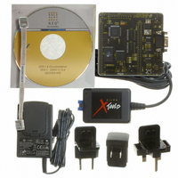
DEV KIT FOR Z16F ZNEO
Manufacturer
Zilog
Series
ZNEO™r
Type
MCUr
Datasheets
1.Z16F2800100ZCOG.pdf
(2 pages)
2.Z16F2800100ZCOG.pdf
(30 pages)
3.Z16F2800100ZCOG.pdf
(388 pages)
Specifications of Z16F2800100ZCOG
Contents
Evaluation Board, Software and Documentation
For Use With/related Products
Z16F Series
For Use With
269-4661 - KIT ACC ETHERNET SMART CABLE
Lead Free Status / RoHS Status
Lead free / RoHS Compliant
Other names
269-4537


PS022008-0810
2. Write to the timer reload high and low byte registers to set the starting count value.
3. Write to the timer reload high and low byte registers to set the Reload value.
4. Enable the timer interrupt, if appropriate, and set the timer interrupt priority by writing
5. Configure the associated GPIO port pin for the timer input alternate function
6. When using the timer output function, configure the associated GPIO port pin for the
7. Write to the timer control 1 register to enable the timer.
PWM SINGLE and DUAL OUTPUT Modes
In PWM SINGLE OUTPUT mode, the timer outputs a PWM output signal through a
GPIO Port pin. In PWM DUAL OUTPUT mode, the timer outputs a PWM output signal
and also its complement through two GPIO port pins. The timer first counts up to the
16-bit PWM match value stored in the timer PWM high and low byte registers. When the
timer count value matches the PWM value, the timer output toggles. The timer continues
counting until it reaches the Reload value stored in the timer reload high and low byte
registers. When it reaches the Reload value, the timer generates an interrupt. The count
value in the timer high and low byte registers is reset to
The timer output signal begins with value =
timer value matches the PWM value. The timer output signal returns to
timer reaches the Reload value and is reset to
In PWM DUAL OUTPUT mode, the timer also generates a second PWM output signal,
timer output complement (TOUT). A programmable deadband is configured (
to delay (0 to 128 system clock cycles) the Low to a High (inactive to active) output
transitions on these two pins. This configuration ensures a time gap between the
deassertion of one PWM output to the assertion of its complement.
Follow the steps below to configure a timer for PWM SINGLE or DUAL OUTPUT mode
and initiate the PWM operation:
1. Write to the timer control registers to:
This affects only the first pass in the COUNTER modes. After the first timer Reload,
counting always begins at the reset value of
to the relevant interrupt registers.
(COUNTER mode).
timer output alternate function.
–
–
–
–
–
Disable the timer.
Configure the timer for the selected PWM mode.
Set the prescale value.
Set the initial logic level (High or Low) and PWM High or Low transition for the
timer output alternate function with the TPOL bit.
Set the deadband delay (DUAL OUTPUT mode) with the
P R E L I M I N A R Y
TPOL
0001H
0001H
and then transits to
.
.
0001H
and counting resumes.
Product Specification
PWMD
ZNEO
TPOL
TPOL
field.
, when the
Z16F Series
PWMD
after the
Timers
field)
101
Related parts for Z16F2800100ZCOG
Image
Part Number
Description
Manufacturer
Datasheet
Request
R

Part Number:
Description:
Communication Controllers, ZILOG INTELLIGENT PERIPHERAL CONTROLLER (ZIP)
Manufacturer:
Zilog, Inc.
Datasheet:

Part Number:
Description:
KIT DEV FOR Z8 ENCORE 16K TO 64K
Manufacturer:
Zilog
Datasheet:

Part Number:
Description:
KIT DEV Z8 ENCORE XP 28-PIN
Manufacturer:
Zilog
Datasheet:

Part Number:
Description:
DEV KIT FOR Z8 ENCORE 8K/4K
Manufacturer:
Zilog
Datasheet:

Part Number:
Description:
KIT DEV Z8 ENCORE XP 28-PIN
Manufacturer:
Zilog
Datasheet:

Part Number:
Description:
DEV KIT FOR Z8 ENCORE 4K TO 8K
Manufacturer:
Zilog
Datasheet:
Part Number:
Description:
CMOS Z8 microcontroller. ROM 16 Kbytes, RAM 256 bytes, speed 16 MHz, 32 lines I/O, 3.0V to 5.5V
Manufacturer:
Zilog, Inc.
Datasheet:
Part Number:
Description:
Low-cost microcontroller. 512 bytes ROM, 61 bytes RAM, 8 MHz
Manufacturer:
Zilog, Inc.
Datasheet:
Part Number:
Description:
Z8 4K OTP Microcontroller
Manufacturer:
Zilog, Inc.
Datasheet:
Part Number:
Description:
CMOS SUPER8 ROMLESS MCU
Manufacturer:
Zilog, Inc.
Datasheet:
Part Number:
Description:
SL1866 CMOSZ8 OTP Microcontroller
Manufacturer:
Zilog, Inc.
Datasheet:
Part Number:
Description:
SL1866 CMOSZ8 OTP Microcontroller
Manufacturer:
Zilog, Inc.
Datasheet:
Part Number:
Description:
OTP (KB) = 1, RAM = 125, Speed = 12, I/O = 14, 8-bit Timers = 2, Comm Interfaces Other Features = Por, LV Protect, Voltage = 4.5-5.5V
Manufacturer:
Zilog, Inc.
Datasheet:
Part Number:
Description:
Manufacturer:
Zilog, Inc.
Datasheet: