Z16F2800100ZCOG Zilog, Z16F2800100ZCOG Datasheet - Page 126
Z16F2800100ZCOG
Manufacturer Part Number
Z16F2800100ZCOG
Description
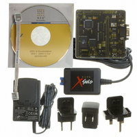
DEV KIT FOR Z16F ZNEO
Manufacturer
Zilog
Series
ZNEO™r
Type
MCUr
Datasheets
1.Z16F2800100ZCOG.pdf
(2 pages)
2.Z16F2800100ZCOG.pdf
(30 pages)
3.Z16F2800100ZCOG.pdf
(388 pages)
Specifications of Z16F2800100ZCOG
Contents
Evaluation Board, Software and Documentation
For Use With/related Products
Z16F Series
For Use With
269-4661 - KIT ACC ETHERNET SMART CABLE
Lead Free Status / RoHS Status
Lead free / RoHS Compliant
Other names
269-4537


PS022008-0810
Bit Position
[6]
TPOL
Value (H) Description
Timer Input/Output Polarity
This bit is a fu nction of the cur rent operating mode of the timer. It
determines the polarity of the input and/or output signal. When the timer is
disabled, the timer output signal is set to the value of this bit.
ONE-SHOT mode —If the timer is enabled, the timer output signal pulses
(changes state) for one system clock cycle after timer Reload.
CONTINUOUS mode—If the timer is enabled, the timer output signal is
complemented after timer Reload.
COUNTER mode—If the timer is enabled, the timer output signal is
complemented after timer reload.
0 = Count occurs on the rising edge of the timer input signal.
1 = Count occurs on the falling edge of the timer input signal.
PWM SINGLE OUTPUT mode—When enabled, the timer output is forced
to TPOL after PWM count match and forced back to TPOL after Reload.
CAPTURE mode—If the timer is enabled, the timer output signal is
complemented after timer Reload.
0 = Count is captured on the rising edge of the timer input signal.
1 = Count is captured on the falling edge of the timer input signal.
COMPARE mode—The timer output signal is complemented after timer
Reload.
GATED mode—The timer output signal is complemented after timer
Reload.
0 = Timer counts when the timer input signal is High and interrupts are
generated on the falling edge of the timer input.
1 = Timer counts when the timer input signal is Low and interrupts are
generated on the rising edge of the timer input.
CAPTURE/COMPARE mode—If the timer is enabled, the timer output
signal is complemented after timer Reload.
0 = Counting starts on the first rising edge of the timer Input signal.
The current count is captured on subsequent rising edges of the timer
input signal.
1 = Counting starts on the first falling edge of the timer input signal.
The current count is captured on subsequent falling edges of the timer
input signal.
P R E L I M I N A R Y
Product Specification
ZNEO
Z16F Series
Timers
111
Related parts for Z16F2800100ZCOG
Image
Part Number
Description
Manufacturer
Datasheet
Request
R

Part Number:
Description:
Communication Controllers, ZILOG INTELLIGENT PERIPHERAL CONTROLLER (ZIP)
Manufacturer:
Zilog, Inc.
Datasheet:

Part Number:
Description:
KIT DEV FOR Z8 ENCORE 16K TO 64K
Manufacturer:
Zilog
Datasheet:

Part Number:
Description:
KIT DEV Z8 ENCORE XP 28-PIN
Manufacturer:
Zilog
Datasheet:

Part Number:
Description:
DEV KIT FOR Z8 ENCORE 8K/4K
Manufacturer:
Zilog
Datasheet:

Part Number:
Description:
KIT DEV Z8 ENCORE XP 28-PIN
Manufacturer:
Zilog
Datasheet:

Part Number:
Description:
DEV KIT FOR Z8 ENCORE 4K TO 8K
Manufacturer:
Zilog
Datasheet:
Part Number:
Description:
CMOS Z8 microcontroller. ROM 16 Kbytes, RAM 256 bytes, speed 16 MHz, 32 lines I/O, 3.0V to 5.5V
Manufacturer:
Zilog, Inc.
Datasheet:
Part Number:
Description:
Low-cost microcontroller. 512 bytes ROM, 61 bytes RAM, 8 MHz
Manufacturer:
Zilog, Inc.
Datasheet:
Part Number:
Description:
Z8 4K OTP Microcontroller
Manufacturer:
Zilog, Inc.
Datasheet:
Part Number:
Description:
CMOS SUPER8 ROMLESS MCU
Manufacturer:
Zilog, Inc.
Datasheet:
Part Number:
Description:
SL1866 CMOSZ8 OTP Microcontroller
Manufacturer:
Zilog, Inc.
Datasheet:
Part Number:
Description:
SL1866 CMOSZ8 OTP Microcontroller
Manufacturer:
Zilog, Inc.
Datasheet:
Part Number:
Description:
OTP (KB) = 1, RAM = 125, Speed = 12, I/O = 14, 8-bit Timers = 2, Comm Interfaces Other Features = Por, LV Protect, Voltage = 4.5-5.5V
Manufacturer:
Zilog, Inc.
Datasheet:
Part Number:
Description:
Manufacturer:
Zilog, Inc.
Datasheet: