Z16F2800100ZCOG Zilog, Z16F2800100ZCOG Datasheet - Page 334
Z16F2800100ZCOG
Manufacturer Part Number
Z16F2800100ZCOG
Description
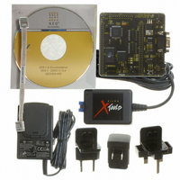
DEV KIT FOR Z16F ZNEO
Manufacturer
Zilog
Series
ZNEO™r
Type
MCUr
Datasheets
1.Z16F2800100ZCOG.pdf
(2 pages)
2.Z16F2800100ZCOG.pdf
(30 pages)
3.Z16F2800100ZCOG.pdf
(388 pages)
Specifications of Z16F2800100ZCOG
Contents
Evaluation Board, Software and Documentation
For Use With/related Products
Z16F Series
For Use With
269-4661 - KIT ACC ETHERNET SMART CABLE
Lead Free Status / RoHS Status
Lead free / RoHS Compliant
Other names
269-4537


®
ZNEO
Z16F Series
Product Specification
318
TDH—Transmit drive high
This control bit causes the interface to drive the line high when a logic 1 is being transmit-
ted. If OE is zero, the line stops being driven when the input is high or at the center of the
bit, whichever is first. If OE is one, the line is driven high for one clock cycle. This bit is
ignored if Debug Mode is zero and the UART is disabled.
0 = Transmit Drive High disabled.
1 = Transmit Drive High enabled.
HDS—High drive strength
This control bit enabled high drive strength for the output driver.
0 = Low Drive Strength
1 = High Drive Strength
TXFC—Transmitter start bit flow control
This control bit enables start bit flow control on the transmitter. The transmitter waits until
a remote device sends a start bit before transmitting its data.
0 = Transmitter start bit flow control disabled.
1 = Transmitter start bit flow control enabled.
NBEN—9-bit mode enable
This control bit enables transmission and reception of a ninth data bit.
0 = Nine bit mode disabled.
1 = Nine bit mode enabled.
NB—Value of ninth bit
This bit is the value of the ninth data bit. When written, this reflects the ninth data bit that
will be transmitted if nine bit mode is enabled. When read, this bit reflects the value of the
ninth bit of the last nine bit character received.
0 = Ninth bit is zero.
1 = Ninth bit is one.
OUT—Output state
This control bit sets the state of the output transceiver. If the UART is enabled, this bit
must be set to one to idle high. Clearing this bit to zero when the UART is enabled will
transmit a break condition. If the UART is disabled, this logic value will be driven onto the
pin if OE is set. This bit is ignored in Debug Mode.
0 = Transmit Break if UART enabled. Drive Low if UART disabled and output enabled.
1 = Idle High if UART enabled. Drive high if UART disabled and output enabled.
PIN—Debug pin
This bit reflects the state of the DBG pin.
0 = DBG pin is Low.
1 = DBG pin is High.
PS022008-0810
P R E L I M I N A R Y
On-Chip Debugger
Related parts for Z16F2800100ZCOG
Image
Part Number
Description
Manufacturer
Datasheet
Request
R

Part Number:
Description:
Communication Controllers, ZILOG INTELLIGENT PERIPHERAL CONTROLLER (ZIP)
Manufacturer:
Zilog, Inc.
Datasheet:

Part Number:
Description:
KIT DEV FOR Z8 ENCORE 16K TO 64K
Manufacturer:
Zilog
Datasheet:

Part Number:
Description:
KIT DEV Z8 ENCORE XP 28-PIN
Manufacturer:
Zilog
Datasheet:

Part Number:
Description:
DEV KIT FOR Z8 ENCORE 8K/4K
Manufacturer:
Zilog
Datasheet:

Part Number:
Description:
KIT DEV Z8 ENCORE XP 28-PIN
Manufacturer:
Zilog
Datasheet:

Part Number:
Description:
DEV KIT FOR Z8 ENCORE 4K TO 8K
Manufacturer:
Zilog
Datasheet:
Part Number:
Description:
CMOS Z8 microcontroller. ROM 16 Kbytes, RAM 256 bytes, speed 16 MHz, 32 lines I/O, 3.0V to 5.5V
Manufacturer:
Zilog, Inc.
Datasheet:
Part Number:
Description:
Low-cost microcontroller. 512 bytes ROM, 61 bytes RAM, 8 MHz
Manufacturer:
Zilog, Inc.
Datasheet:
Part Number:
Description:
Z8 4K OTP Microcontroller
Manufacturer:
Zilog, Inc.
Datasheet:
Part Number:
Description:
CMOS SUPER8 ROMLESS MCU
Manufacturer:
Zilog, Inc.
Datasheet:
Part Number:
Description:
SL1866 CMOSZ8 OTP Microcontroller
Manufacturer:
Zilog, Inc.
Datasheet:
Part Number:
Description:
SL1866 CMOSZ8 OTP Microcontroller
Manufacturer:
Zilog, Inc.
Datasheet:
Part Number:
Description:
OTP (KB) = 1, RAM = 125, Speed = 12, I/O = 14, 8-bit Timers = 2, Comm Interfaces Other Features = Por, LV Protect, Voltage = 4.5-5.5V
Manufacturer:
Zilog, Inc.
Datasheet:
Part Number:
Description:
Manufacturer:
Zilog, Inc.
Datasheet: