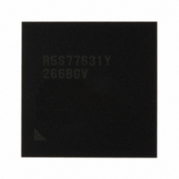
R5S77631Y266BGV Renesas Electronics America, R5S77631Y266BGV Datasheet - Page 42

R5S77631Y266BGV
Manufacturer Part Number
R5S77631Y266BGV
Description
IC SUPERH MPU ROMLESS 499BGA
Manufacturer
Renesas Electronics America
Series
SuperH® SH7780r
Datasheet
1.R5S77631Y266BGV.pdf
(2056 pages)
Specifications of R5S77631Y266BGV
Core Processor
SH-4A
Core Size
32-Bit
Speed
266MHz
Connectivity
Audio Codec, I²C, MMC, SCI, SIM, SIO, SSI, USB
Peripherals
DMA, LCD, POR, WDT
Number Of I /o
107
Program Memory Type
ROMless
Ram Size
16K x 8
Voltage - Supply (vcc/vdd)
1.15 V ~ 1.35 V
Data Converters
A/D 4x10b; D/A 2x8b
Oscillator Type
External
Operating Temperature
-20°C ~ 75°C
Package / Case
499-BGA
Lead Free Status / RoHS Status
Lead free / RoHS Compliant
Eeprom Size
-
Program Memory Size
-
Available stocks
Company
Part Number
Manufacturer
Quantity
Price
Company:
Part Number:
R5S77631Y266BGV
Manufacturer:
Renesas Electronics America
Quantity:
10 000
- Current page: 42 of 2056
- Download datasheet (10Mb)
Figure 6.9 Flowchart of Memory Access Using UTLB.............................................................. 160
Figure 6.10 Flowchart of Memory Access Using ITLB ............................................................. 161
Figure 6.11 Operation of LDTLB Instruction............................................................................. 164
Figure 6.12 Memory-Mapped ITLB Address Array................................................................... 173
Figure 6.13 Memory-Mapped ITLB Data Array ........................................................................ 174
Figure 6.14 Memory-Mapped UTLB Address Array ................................................................. 176
Figure 6.15 Memory-Mapped UTLB Data Array....................................................................... 177
Figure 6.16 Physical Address Space (32-Bit Address Extended Mode)..................................... 177
Figure 6.17 PMB Configuration ................................................................................................. 179
Figure 6.18 Memory-Mapped PMB Address Array ................................................................... 183
Figure 6.19 Memory-Mapped PMB Data Array......................................................................... 183
Section 7 Caches
Figure 7.1 Configuration of Operand Cache (OC) ..................................................................... 188
Figure 7.2 Configuration of Instruction Cache (IC) ................................................................... 189
Figure 7.3 Configuration of Write-Back Buffer ......................................................................... 201
Figure 7.4 Configuration of Write-Through Buffer.................................................................... 201
Figure 7.5 Memory-Mapped IC Address Array ......................................................................... 207
Figure 7.6 Memory-Mapped IC Data Array ............................................................................... 208
Figure 7.7 Memory-Mapped OC Address Array........................................................................ 210
Figure 7.8 Memory-Mapped OC Data Array ............................................................................. 211
Figure 7.9 Store Queue Configuration........................................................................................ 212
Section 9 Interrupt Controller (INTC)
Figure 9.1 Block Diagram of INTC............................................................................................ 234
Figure 9.2 Example of IRL Interrupt Connection....................................................................... 293
Figure 9.3 On-chip Module Interrupt Priority ............................................................................ 296
Figure 9.4 Interrupt Operation Flowchart................................................................................... 306
Figure 9.5 Example of Interrupt Handling Routine .................................................................... 309
Section 10 SuperHyway Bus Bridge (SBR)
Figure 10.1 SBR Block Diagram................................................................................................ 313
Figure 10.2 Bus Arbitration by the SBR..................................................................................... 317
Section 11 Local Bus State Controller (LBSC)
Figure 11.1 LBSC Block Diagram ............................................................................................. 321
Figure 11.2 Correspondence between Virtual Address Space and External Memory Space...... 325
Figure 11.3 External Memory Space Allocation ........................................................................ 327
Figure 11.4 RDY Sampling Timings with ASYNCn Settings
(Two Wait Cycles Inserted by CSnWCR.).............................................................. 340
Figure 11.5 Basic Timing of SRAM Interface............................................................................ 367
Figure 11.6 Example of 32-Bit Data-Width SRAM Connection................................................ 368
Rev. 2.00 May 22, 2009 Page xl of lxviii
Related parts for R5S77631Y266BGV
Image
Part Number
Description
Manufacturer
Datasheet
Request
R

Part Number:
Description:
KIT STARTER FOR M16C/29
Manufacturer:
Renesas Electronics America
Datasheet:

Part Number:
Description:
KIT STARTER FOR R8C/2D
Manufacturer:
Renesas Electronics America
Datasheet:

Part Number:
Description:
R0K33062P STARTER KIT
Manufacturer:
Renesas Electronics America
Datasheet:

Part Number:
Description:
KIT STARTER FOR R8C/23 E8A
Manufacturer:
Renesas Electronics America
Datasheet:

Part Number:
Description:
KIT STARTER FOR R8C/25
Manufacturer:
Renesas Electronics America
Datasheet:

Part Number:
Description:
KIT STARTER H8S2456 SHARPE DSPLY
Manufacturer:
Renesas Electronics America
Datasheet:

Part Number:
Description:
KIT STARTER FOR R8C38C
Manufacturer:
Renesas Electronics America
Datasheet:

Part Number:
Description:
KIT STARTER FOR R8C35C
Manufacturer:
Renesas Electronics America
Datasheet:

Part Number:
Description:
KIT STARTER FOR R8CL3AC+LCD APPS
Manufacturer:
Renesas Electronics America
Datasheet:

Part Number:
Description:
KIT STARTER FOR RX610
Manufacturer:
Renesas Electronics America
Datasheet:

Part Number:
Description:
KIT STARTER FOR R32C/118
Manufacturer:
Renesas Electronics America
Datasheet:

Part Number:
Description:
KIT DEV RSK-R8C/26-29
Manufacturer:
Renesas Electronics America
Datasheet:

Part Number:
Description:
KIT STARTER FOR SH7124
Manufacturer:
Renesas Electronics America
Datasheet:

Part Number:
Description:
KIT STARTER FOR H8SX/1622
Manufacturer:
Renesas Electronics America
Datasheet:

Part Number:
Description:
KIT DEV FOR SH7203
Manufacturer:
Renesas Electronics America
Datasheet:


