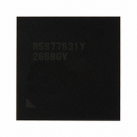
R5S77631Y266BGV Renesas Electronics America, R5S77631Y266BGV Datasheet - Page 54

R5S77631Y266BGV
Manufacturer Part Number
R5S77631Y266BGV
Description
IC SUPERH MPU ROMLESS 499BGA
Manufacturer
Renesas Electronics America
Series
SuperH® SH7780r
Datasheet
1.R5S77631Y266BGV.pdf
(2056 pages)
Specifications of R5S77631Y266BGV
Core Processor
SH-4A
Core Size
32-Bit
Speed
266MHz
Connectivity
Audio Codec, I²C, MMC, SCI, SIM, SIO, SSI, USB
Peripherals
DMA, LCD, POR, WDT
Number Of I /o
107
Program Memory Type
ROMless
Ram Size
16K x 8
Voltage - Supply (vcc/vdd)
1.15 V ~ 1.35 V
Data Converters
A/D 4x10b; D/A 2x8b
Oscillator Type
External
Operating Temperature
-20°C ~ 75°C
Package / Case
499-BGA
Lead Free Status / RoHS Status
Lead free / RoHS Compliant
Eeprom Size
-
Program Memory Size
-
Available stocks
Company
Part Number
Manufacturer
Quantity
Price
Company:
Part Number:
R5S77631Y266BGV
Manufacturer:
Renesas Electronics America
Quantity:
10 000
- Current page: 54 of 2056
- Download datasheet (10Mb)
Figure 34.8 Multichannel Format
Figure 34.9 Basic Sample Format
Figure 34.10 Inverted Clock ..................................................................................................... 1447
Figure 34.11 Inverted Word Select........................................................................................... 1447
Figure 34.12 Inverted Padding Polarity.................................................................................... 1447
Figure 34.13 Padding Bits First, Followed by Serial Data, with Delay.................................... 1448
Figure 34.14 Padding Bits First, Followed by Serial Data, without Delay............................... 1448
Figure 34.15 Serial Data First, Followed by Padding Bits, without Delay............................... 1448
Figure 34.16 Parallel Right Aligned with Delay ...................................................................... 1449
Figure 34.17 Mute Enabled ...................................................................................................... 1449
Figure 34.18 Transition Diagram between Operation Modes................................................... 1450
Figure 34.19 Transmission Using DMA Controller ................................................................. 1452
Figure 34.20 Transmission using Interrupt Data Flow Control ................................................ 1453
Figure 34.21 Reception using DMA Controller ....................................................................... 1455
Figure 34.22 Reception using Interrupt Data Flow Control ..................................................... 1456
Section 35 USB Host Controller (USBH)
Figure 35.1 Block Diagram of USBH ...................................................................................... 1460
Figure 35.2 Connection Example of External Circuit .............................................................. 1495
Section 36 USB Function Controller (USBF)
Figure 36.1 Block Diagram of USBF ....................................................................................... 1498
Figure 36.2 Example of Endpoint Configuration ..................................................................... 1556
Figure 36.3 Cable Connection Operation ................................................................................. 1561
Figure 36.4 Cable Disconnection Operation............................................................................. 1562
Figure 36.5 Setup Stage Operation ........................................................................................... 1563
Figure 36.6 Data Stage (Control-In) Operation ........................................................................ 1564
Figure 36.7 Data Stage (Control-Out) Operation ..................................................................... 1565
Figure 36.8 Status Stage (Control-In) Operation...................................................................... 1566
Figure 36.9 Status Stage (Control-Out) Operation ................................................................... 1567
Figure 36.10 EP1 Bulk-Out Transfer Operation....................................................................... 1568
Figure 36.11 EP2 Bulk-In Transfer Operation ......................................................................... 1569
Figure 36.12 EP3 Interrupt-In Transfer Operation ................................................................... 1571
Figure 36.13 EP4 Isochronous-Out Transfer Operation (SOF is Normal) ............................... 1572
Figure 36.14 EP4 Isochronous-Out Transfer Operation (SOF is Broken)................................ 1573
Figure 36.15 EP5 Isochronous-In Transfer Operation (SOF is Normal) .................................. 1575
Figure 36.16 EP5 Isochronous-In Transfer Operation (SOF in Broken) .................................. 1576
Figure 36.17 Forcible Stall by Application .............................................................................. 1580
Figure 36.18 Automatic Stall by USB Function Controller...................................................... 1582
Rev. 2.00 May 22, 2009 Page lii of lxviii
(4 Channels, with Padding Bits First, Followed by Serial Data, with Padding) .... 1445
(Transmit Mode with Example System/Data Word Length)................................. 1446
Related parts for R5S77631Y266BGV
Image
Part Number
Description
Manufacturer
Datasheet
Request
R

Part Number:
Description:
KIT STARTER FOR M16C/29
Manufacturer:
Renesas Electronics America
Datasheet:

Part Number:
Description:
KIT STARTER FOR R8C/2D
Manufacturer:
Renesas Electronics America
Datasheet:

Part Number:
Description:
R0K33062P STARTER KIT
Manufacturer:
Renesas Electronics America
Datasheet:

Part Number:
Description:
KIT STARTER FOR R8C/23 E8A
Manufacturer:
Renesas Electronics America
Datasheet:

Part Number:
Description:
KIT STARTER FOR R8C/25
Manufacturer:
Renesas Electronics America
Datasheet:

Part Number:
Description:
KIT STARTER H8S2456 SHARPE DSPLY
Manufacturer:
Renesas Electronics America
Datasheet:

Part Number:
Description:
KIT STARTER FOR R8C38C
Manufacturer:
Renesas Electronics America
Datasheet:

Part Number:
Description:
KIT STARTER FOR R8C35C
Manufacturer:
Renesas Electronics America
Datasheet:

Part Number:
Description:
KIT STARTER FOR R8CL3AC+LCD APPS
Manufacturer:
Renesas Electronics America
Datasheet:

Part Number:
Description:
KIT STARTER FOR RX610
Manufacturer:
Renesas Electronics America
Datasheet:

Part Number:
Description:
KIT STARTER FOR R32C/118
Manufacturer:
Renesas Electronics America
Datasheet:

Part Number:
Description:
KIT DEV RSK-R8C/26-29
Manufacturer:
Renesas Electronics America
Datasheet:

Part Number:
Description:
KIT STARTER FOR SH7124
Manufacturer:
Renesas Electronics America
Datasheet:

Part Number:
Description:
KIT STARTER FOR H8SX/1622
Manufacturer:
Renesas Electronics America
Datasheet:

Part Number:
Description:
KIT DEV FOR SH7203
Manufacturer:
Renesas Electronics America
Datasheet:


