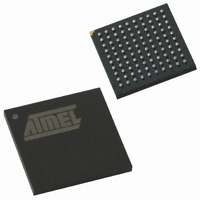
AT89C51SND2C-7FTUL Atmel, AT89C51SND2C-7FTUL Datasheet - Page 160

AT89C51SND2C-7FTUL
Manufacturer Part Number
AT89C51SND2C-7FTUL
Description
IC 8051 MCU FLASH 64K MP3 100BGA
Manufacturer
Atmel
Series
89Cr
Datasheet
1.AT89C51SND2C-7FTUL.pdf
(242 pages)
Specifications of AT89C51SND2C-7FTUL
Core Processor
8051
Core Size
8-Bit
Speed
40MHz
Connectivity
I²C, IDE/ATAPI, MMC, SPI, UART/USART, USB
Peripherals
Audio, I²S, MP3, PCM, POR, WDT
Number Of I /o
32
Program Memory Size
64KB (64K x 8)
Program Memory Type
FLASH
Ram Size
2.25K x 8
Voltage - Supply (vcc/vdd)
2.7 V ~ 3.3 V
Data Converters
A/D 2x10b; D/A 2x20b
Oscillator Type
Internal
Operating Temperature
-40°C ~ 85°C
Package / Case
100-TFBGA
Data Bus Width
8 bit
Data Ram Size
2.25 KB
Interface Type
ATAPI, I2S, IDE, SPI, UART, USB
Maximum Clock Frequency
40 MHz
Number Of Programmable I/os
32
Number Of Timers
2
Maximum Operating Temperature
+ 85 C
Mounting Style
SMD/SMT
Minimum Operating Temperature
- 40 C
Lead Free Status / RoHS Status
Lead free / RoHS Compliant
Eeprom Size
-
Lead Free Status / Rohs Status
Details
Other names
AT89C51SND2C7FTUL
Available stocks
Company
Part Number
Manufacturer
Quantity
Price
Company:
Part Number:
AT89C51SND2C-7FTUL
Manufacturer:
ATMEL
Quantity:
4 371
- Current page: 160 of 242
- Download datasheet (3Mb)
19.1.6
19.2
19.3
19.3.1
160
Interrupt
Configuration
AT8xC51SND2C/MP3B
Error Conditions
Master Configuration
Figure 19-7. SS Timing Diagram
The following flags signal the SPI error conditions:
•
•
•
The SPI handles 2 interrupt sources that are the “end of transfer” and the “mode fault” flags.
As shown in Figure 19-8, these flags are combined toghether to appear as a single interrupt
source for the C51 core. The SPIF flag is set at the end of an 8-bit shift in and out and is cleared
by reading SPSTA and then reading from or writing to SPDAT.
The MODF flag is set in case of mode fault error and is cleared by reading SPSTA and then writ-
ing to SPCON.
The SPI interrupt is enabled by setting ESPI bit in IEN1 register. This assumes interrupts are
globally enabled by setting EA bit in IEN0 register.
Figure 19-8. SPI Interrupt System
The SPI configuration is made through SPCON.
The SPI operates in master mode when the MSTR bit in SPCON is set.
MODF in SPSTA signals a mode fault.
MODF flag is relevant only in master mode when SS usage is enabled (SSDIS bit cleared).
It signals when set that an other master on the bus has asserted SS pin and so, may create
a conflict on the bus with 2 master sending data at the same time.
A mode fault automatically disables the SPI (SPEN cleared) and configures the SPI in slave
mode (MSTR cleared).
MODF flag can trigger an interrupt as explained in Section "Interrupt", page 160.
MODF flag is cleared by reading SPSTA and re-configuring SPI by writing to SPCON.
WCOL in SPSTA signals a write collision.
WCOL flag is set when SPDAT is loaded while a transfer is on-going. In this case data is not
written to SPDAT and transfer continue uninterrupted. WCOL flag does not trigger any
interrupt and is relevant jointly with SPIF flag.
WCOL flag is cleared after reading SPSTA and writing new data to SPDAT while no transfer
is on-going.
SS (CPHA = 0)
SS (CPHA = 1)
SI/SO
SPSTA.7
SPSTA.4
MODF
SPIF
Byte 1
IEN1.2
ESPI
Byte 2
SPI Controller
Interrupt Request
Byte 3
4341H–MP3–10/07
Related parts for AT89C51SND2C-7FTUL
Image
Part Number
Description
Manufacturer
Datasheet
Request
R

Part Number:
Description:
DEV KIT FOR AVR/AVR32
Manufacturer:
Atmel
Datasheet:

Part Number:
Description:
INTERVAL AND WIPE/WASH WIPER CONTROL IC WITH DELAY
Manufacturer:
ATMEL Corporation
Datasheet:

Part Number:
Description:
Low-Voltage Voice-Switched IC for Hands-Free Operation
Manufacturer:
ATMEL Corporation
Datasheet:

Part Number:
Description:
MONOLITHIC INTEGRATED FEATUREPHONE CIRCUIT
Manufacturer:
ATMEL Corporation
Datasheet:

Part Number:
Description:
AM-FM Receiver IC U4255BM-M
Manufacturer:
ATMEL Corporation
Datasheet:

Part Number:
Description:
Monolithic Integrated Feature Phone Circuit
Manufacturer:
ATMEL Corporation
Datasheet:

Part Number:
Description:
Multistandard Video-IF and Quasi Parallel Sound Processing
Manufacturer:
ATMEL Corporation
Datasheet:

Part Number:
Description:
High-performance EE PLD
Manufacturer:
ATMEL Corporation
Datasheet:

Part Number:
Description:
8-bit Flash Microcontroller
Manufacturer:
ATMEL Corporation
Datasheet:

Part Number:
Description:
2-Wire Serial EEPROM
Manufacturer:
ATMEL Corporation
Datasheet:


