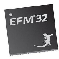
EFM32TG210F32 Energy Micro, EFM32TG210F32 Datasheet - Page 109

EFM32TG210F32
Manufacturer Part Number
EFM32TG210F32
Description
MCU 32BIT 32KB FLASH 32-QFN
Manufacturer
Energy Micro
Series
Tiny Geckor
Specifications of EFM32TG210F32
Core Processor
ARM® Cortex-M3™
Core Size
32-Bit
Speed
32MHz
Connectivity
EBI/EMI, I²C, IrDA, SmartCard, SPI, UART/USART
Peripherals
Brown-out Detect/Reset, DMA, POR, PWM, WDT
Number Of I /o
24
Program Memory Size
32KB (32K x 8)
Program Memory Type
FLASH
Ram Size
4K x 8
Voltage - Supply (vcc/vdd)
1.8 V ~ 3.8 V
Data Converters
A/D 4x12b, D/A 1x12b
Oscillator Type
External
Operating Temperature
-40°C ~ 85°C
Package / Case
32-VQFN Exposed Pad
Processor Series
EFM32
Core
ARM Cortex-M3
Data Bus Width
32 bit
Data Ram Size
32 KB
Interface Type
UART, I2C, SPI
Maximum Clock Frequency
32 MHz
Number Of Programmable I/os
17
Number Of Timers
1
Operating Supply Voltage
1.8 V to 3.8 V
Maximum Operating Temperature
+ 85 C
Mounting Style
SMD/SMT
Processor To Be Evaluated
EFM32TG210
Lead Free Status / RoHS Status
Lead free / RoHS Compliant
Eeprom Size
-
Lead Free Status / Rohs Status
Details
- Current page: 109 of 522
- Download datasheet (9Mb)
11.5.5 CMU_LFRCOCTRL - LFRCO Control Register
11.5.6 CMU_AUXHFRCOCTRL - AUXHFRCO Control Register
31:7
6:0
31:11
10:8
7:0
Offset
0x010
Reset
Access
Name
Bit
Offset
0x014
Reset
Access
Name
Bit
2010-12-21 - d0034_Rev0.90
Reserved
TUNING
Writing this field adjusts the LFRCO frequency (the higher value, the higher frequency). This field is updated with the production
calibrated value during reset, and the reset value might therefore vary between devices.
Reserved
BAND
Write this field to set the frequency band in which the AUXHFRCO is to operate. When changing this setting there will be no glitches
on the HFRCO output, hence it is safe to change this setting even while the system is using the AUXHFRCO. To ensure an accurate
frequency, the AUXTUNING value should also be written when changing the frequency band. The calibrated tuning value for the
different bands can be read from the Device Information page. Flash erase and write use this clock. If it is changed to another value
than the default, MSC_TIMEBASE must also be configured to ensure correct flash erase and write operation.
TUNING
This value has been set during calibration and should not be changed.
Name
Name
Value
0
1
2
3
6
7
Mode
14MHZ
11MHZ
7MHZ
1MHZ
28MHZ
21MHZ
0x40
0x0
0x80
Reset
To ensure compatibility with future devices, always write bits to 0. More information in Section 2.1 (p. 3)
Reset
To ensure compatibility with future devices, always write bits to 0. More information in Section 2.1 (p. 3)
RW
RW
RW
Access
Access
Description
14 MHz. NOTE: Also set the TUNING value (bits 7:0) when changing band.
11 MHz. NOTE: Also set the TUNING value (bits 7:0) when changing band.
7 MHz. NOTE: Also set the TUNING value (bits 7:0) when changing band.
1 MHz. NOTE: Also set the TUNING value (bits 7:0) when changing band.
28 MHz. NOTE: Also set the TUNING value (bits 7:0) when changing band.
21 MHz. NOTE: Also set the TUNING value (bits 7:0) when changing band.
...the world's most energy friendly microcontrollers
109
Bit Position
Bit Position
LFRCO Tuning Value
AUXHFRCO Band Select
AUXHFRCO Tuning Value
Description
Description
www.energymicro.com
Related parts for EFM32TG210F32
Image
Part Number
Description
Manufacturer
Datasheet
Request
R

Part Number:
Description:
KIT STARTER EFM32 GECKO
Manufacturer:
Energy Micro
Datasheet:

Part Number:
Description:
KIT DEV EFM32 GECKO LCD SUPPORT
Manufacturer:
Energy Micro
Datasheet:

Part Number:
Description:
BOARD PROTOTYPING FOR EFM32
Manufacturer:
Energy Micro
Datasheet:

Part Number:
Description:
KIT DEVELOPMENT EFM32 GECKO
Manufacturer:
Energy Micro
Datasheet:

Part Number:
Description:
MCU, MPU & DSP Development Tools TG840 Sample Kit
Manufacturer:
Energy Micro
Datasheet:

Part Number:
Description:
MCU, MPU & DSP Development Tools TG Starter Kit
Manufacturer:
Energy Micro
Datasheet:

Part Number:
Description:
MCU, MPU & DSP Development Tools TG108 Sample Kit
Manufacturer:
Energy Micro

Part Number:
Description:
MCU, MPU & DSP Development Tools TG210 Sample Kit
Manufacturer:
Energy Micro
Datasheet:

Part Number:
Description:
MCU, MPU & DSP Development Tools TG822 Sample Kit
Manufacturer:
Energy Micro
Datasheet:

Part Number:
Description:
MCU, MPU & DSP Development Tools TG230 Sample Kit
Manufacturer:
Energy Micro

Part Number:
Description:
SAMPLE KIT (SMALL BOX - CONTAINING 2 DEVICES)
Manufacturer:
Energy Micro

Part Number:
Description:
SAMPLE KIT (SMALL BOX - CONTAINING 2 DEVICES)
Manufacturer:
Energy Micro


