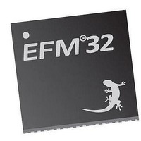
EFM32TG210F32 Energy Micro, EFM32TG210F32 Datasheet - Page 255

EFM32TG210F32
Manufacturer Part Number
EFM32TG210F32
Description
MCU 32BIT 32KB FLASH 32-QFN
Manufacturer
Energy Micro
Series
Tiny Geckor
Specifications of EFM32TG210F32
Core Processor
ARM® Cortex-M3™
Core Size
32-Bit
Speed
32MHz
Connectivity
EBI/EMI, I²C, IrDA, SmartCard, SPI, UART/USART
Peripherals
Brown-out Detect/Reset, DMA, POR, PWM, WDT
Number Of I /o
24
Program Memory Size
32KB (32K x 8)
Program Memory Type
FLASH
Ram Size
4K x 8
Voltage - Supply (vcc/vdd)
1.8 V ~ 3.8 V
Data Converters
A/D 4x12b, D/A 1x12b
Oscillator Type
External
Operating Temperature
-40°C ~ 85°C
Package / Case
32-VQFN Exposed Pad
Processor Series
EFM32
Core
ARM Cortex-M3
Data Bus Width
32 bit
Data Ram Size
32 KB
Interface Type
UART, I2C, SPI
Maximum Clock Frequency
32 MHz
Number Of Programmable I/os
17
Number Of Timers
1
Operating Supply Voltage
1.8 V to 3.8 V
Maximum Operating Temperature
+ 85 C
Mounting Style
SMD/SMT
Processor To Be Evaluated
EFM32TG210
Lead Free Status / RoHS Status
Lead free / RoHS Compliant
Eeprom Size
-
Lead Free Status / Rohs Status
Details
- Current page: 255 of 522
- Download datasheet (9Mb)
17.3.2.6.1 2x Count Mode
17.3.2.7 Up/Down-count (Dual-slope) PWM
2010-12-21 - d0034_Rev0.90
The PWM frequency is given by Equation 17.4 (p. 255) :
TIMER Up-count PWM Frequency Equation
The high duty cycle is given by Equation 17.5 (p. 255)
TIMER Up-count Duty Cycle Equation
When the Timer is set in 2x mode, the TIMER will count up by two. This will in effect make any odd Top
value be rounded down to the closest even number. Similarly, any odd CC value will generate a match
on the closest lower even value as shown in Figure 17.19 (p. 255)
Figure 17.19. TIMER CC out in 2x mode
The mode is enabled by setting the X2CNT field in TIMERn_CTRL register. The intended use of the
2x mode is to generate 2x PWM frequency when the Compare/Capture channel is put in PWM mode.
Since the PWM output is updated on both edges of the clock, frequency prescaling will result in incorrect
result in this mode. The PWM resolution (in bits) is then given by Equation 17.6 (p. 255) .
TIMER 2x PWM Resolution Equation
The PWM frequency is given by Equation 17.7 (p. 255) :
TIMER 2x Mode PWM Frequency Equation( Up-count)
The high duty cycle is given by Equation 17.8 (p. 255)
TIMER 2x Mode Duty Cycle Equation
If the counter is set to up-down count and the Compare/Capture channel is put in PWM mode, dual
slope PWM output will be generated by Figure 17.20 (p. 256) .The resolution (in bits) is given by
Equation 17.9 (p. 256) .
CC Out
Clock
Top = 5
CC = 1
0
f
PWM
2
f
PWM
up/down
R
4
2xmode
PWM
R
= f
PWM
DS
HFPERCLK
0
= 2 x f
2xmode
DS
2xmode
up
up
= log(TOP+1)/log(2)
= log(TOP/2+1)/log(2)
2
HFPERCLK
= CCVx/TOP
/ ( 2^PRESC x (TOP + 1)
= CCVx/TOP
4
...the world's most energy friendly microcontrollers
255
/ floor(TOP/2)+1
0
Top = 5
CC = 2
0
2
4
www.energymicro.com
0
2
4
(17.3)
(17.4)
(17.5)
(17.6)
(17.7)
(17.8)
0
Related parts for EFM32TG210F32
Image
Part Number
Description
Manufacturer
Datasheet
Request
R

Part Number:
Description:
KIT STARTER EFM32 GECKO
Manufacturer:
Energy Micro
Datasheet:

Part Number:
Description:
KIT DEV EFM32 GECKO LCD SUPPORT
Manufacturer:
Energy Micro
Datasheet:

Part Number:
Description:
BOARD PROTOTYPING FOR EFM32
Manufacturer:
Energy Micro
Datasheet:

Part Number:
Description:
KIT DEVELOPMENT EFM32 GECKO
Manufacturer:
Energy Micro
Datasheet:

Part Number:
Description:
MCU, MPU & DSP Development Tools TG840 Sample Kit
Manufacturer:
Energy Micro
Datasheet:

Part Number:
Description:
MCU, MPU & DSP Development Tools TG Starter Kit
Manufacturer:
Energy Micro
Datasheet:

Part Number:
Description:
MCU, MPU & DSP Development Tools TG108 Sample Kit
Manufacturer:
Energy Micro

Part Number:
Description:
MCU, MPU & DSP Development Tools TG210 Sample Kit
Manufacturer:
Energy Micro
Datasheet:

Part Number:
Description:
MCU, MPU & DSP Development Tools TG822 Sample Kit
Manufacturer:
Energy Micro
Datasheet:

Part Number:
Description:
MCU, MPU & DSP Development Tools TG230 Sample Kit
Manufacturer:
Energy Micro

Part Number:
Description:
SAMPLE KIT (SMALL BOX - CONTAINING 2 DEVICES)
Manufacturer:
Energy Micro

Part Number:
Description:
SAMPLE KIT (SMALL BOX - CONTAINING 2 DEVICES)
Manufacturer:
Energy Micro


