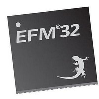
EFM32TG210F32 Energy Micro, EFM32TG210F32 Datasheet - Page 325

EFM32TG210F32
Manufacturer Part Number
EFM32TG210F32
Description
MCU 32BIT 32KB FLASH 32-QFN
Manufacturer
Energy Micro
Series
Tiny Geckor
Specifications of EFM32TG210F32
Core Processor
ARM® Cortex-M3™
Core Size
32-Bit
Speed
32MHz
Connectivity
EBI/EMI, I²C, IrDA, SmartCard, SPI, UART/USART
Peripherals
Brown-out Detect/Reset, DMA, POR, PWM, WDT
Number Of I /o
24
Program Memory Size
32KB (32K x 8)
Program Memory Type
FLASH
Ram Size
4K x 8
Voltage - Supply (vcc/vdd)
1.8 V ~ 3.8 V
Data Converters
A/D 4x12b, D/A 1x12b
Oscillator Type
External
Operating Temperature
-40°C ~ 85°C
Package / Case
32-VQFN Exposed Pad
Processor Series
EFM32
Core
ARM Cortex-M3
Data Bus Width
32 bit
Data Ram Size
32 KB
Interface Type
UART, I2C, SPI
Maximum Clock Frequency
32 MHz
Number Of Programmable I/os
17
Number Of Timers
1
Operating Supply Voltage
1.8 V to 3.8 V
Maximum Operating Temperature
+ 85 C
Mounting Style
SMD/SMT
Processor To Be Evaluated
EFM32TG210
Lead Free Status / RoHS Status
Lead free / RoHS Compliant
Eeprom Size
-
Lead Free Status / Rohs Status
Details
- Current page: 325 of 522
- Download datasheet (9Mb)
21.3.7 Measurement results
2010-12-21 - d0034_Rev0.90
Note
To prevent unnecessary interrupt requests or PRS outputs when the decoder toggles back and forth
between two states, a hysteresis option is available. The hysteresis function is triggered if a type A
transition is preceded by a type B transition, and vice versa. A type A transition is a transition defined in
STx_TCONFA, and a type B transition is a transition defined in STx_TCONFB. When descriptor chaining
is used, a jump to another descriptor will cancel out the hysteresis effect. Figure 21.8 (p. 325) illustrates
how the hysteresis triggers upon state transitions.
Figure 21.8. Decoder hysteresis
The events suppressed by the hysteresis are configured in bit fields HYSTPRS0-2 and HYSTIRQ in
DECCTRL.
• When HYSTPRSx is set, PRS signal x is suppressed when the hysteresis triggers.
• When HYSTIRQ is set, interrupt requests are suppressed when the hysteresis triggers.
Note
Part of the LESENSE RAM is treated as a circular buffer for storage of up to 16 results from sensor
measurements. Each time LESENSE writes data to the result buffer, the result write pointer, PTR_WR,
is incremented. Each time a new result is read through the BUFDATA register, the result read pointer,
PTR_RD, is incremented. The read pointer will not be incremented if there is no valid, unread data in
the result buffer. By default LESENSE will not write additional data to a full result buffer until the data is
read by software or DMA. Setting BUFOW in CTRL enables LESENSE to write to the result buffer, even
if it is full. In this mode, the result read pointer will follow the write pointer if the buffer is full. The result of
this is that data read from the result read register, BUFDATA, is the oldest unread result. The location
pointers are available in PTR. The result buffer has three status flags; BUFDATAV, BUFHALFFULL,
and BUFFULL. The flags indicate when new data is available, when the buffer is half full, and when it is
full, respectively. The interrupt flag BUFDATAV is set when data is available in the buffer. BUFLEVEL
is set when the buffer is either full or halffull, depending on the configuration of BUFIDL in CTRL. If the
result buffer overflows, the BUFOF interrupt flag will be set.
During a scan, the state of each sensor is stored in SCANRES. If a sensor triggers, a 1 is stored in
SCANRES, else a 0 is stored in SCANRES. Whether or not a sensor is said to be triggered depends of
the configuration for the given channel. If SAMPLE is set to ACMP, the sensor is said to be triggered
if the output from the analog comparator is 1 when sensor sampling is performed. If SAMPLE is set to
COUNTER, a sensor is said to be triggered if the LESENSE counter value is greater than or equal, or
3: B transition, hysteresis
If only one transition from a state is used, STx_TCONFA and STx_TCONFB should be
configured equally.
The decoder error interrupt flag, DECERR, is not affected by the hysteresis.
1: B transition, no hysteresis
5: A transition, no hysteresis
2: A transition, hysteresis
State 0
State 1
State 2
State 3
4: A transition, hysteresis
A transition: Transition defined in TCONFA
B transition: Transition defined in TCONFB
...the world's most energy friendly microcontrollers
325
www.energymicro.com
Related parts for EFM32TG210F32
Image
Part Number
Description
Manufacturer
Datasheet
Request
R

Part Number:
Description:
KIT STARTER EFM32 GECKO
Manufacturer:
Energy Micro
Datasheet:

Part Number:
Description:
KIT DEV EFM32 GECKO LCD SUPPORT
Manufacturer:
Energy Micro
Datasheet:

Part Number:
Description:
BOARD PROTOTYPING FOR EFM32
Manufacturer:
Energy Micro
Datasheet:

Part Number:
Description:
KIT DEVELOPMENT EFM32 GECKO
Manufacturer:
Energy Micro
Datasheet:

Part Number:
Description:
MCU, MPU & DSP Development Tools TG840 Sample Kit
Manufacturer:
Energy Micro
Datasheet:

Part Number:
Description:
MCU, MPU & DSP Development Tools TG Starter Kit
Manufacturer:
Energy Micro
Datasheet:

Part Number:
Description:
MCU, MPU & DSP Development Tools TG108 Sample Kit
Manufacturer:
Energy Micro

Part Number:
Description:
MCU, MPU & DSP Development Tools TG210 Sample Kit
Manufacturer:
Energy Micro
Datasheet:

Part Number:
Description:
MCU, MPU & DSP Development Tools TG822 Sample Kit
Manufacturer:
Energy Micro
Datasheet:

Part Number:
Description:
MCU, MPU & DSP Development Tools TG230 Sample Kit
Manufacturer:
Energy Micro

Part Number:
Description:
SAMPLE KIT (SMALL BOX - CONTAINING 2 DEVICES)
Manufacturer:
Energy Micro

Part Number:
Description:
SAMPLE KIT (SMALL BOX - CONTAINING 2 DEVICES)
Manufacturer:
Energy Micro


