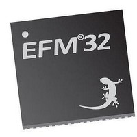
EFM32TG210F32 Energy Micro, EFM32TG210F32 Datasheet - Page 87

EFM32TG210F32
Manufacturer Part Number
EFM32TG210F32
Description
MCU 32BIT 32KB FLASH 32-QFN
Manufacturer
Energy Micro
Series
Tiny Geckor
Specifications of EFM32TG210F32
Core Processor
ARM® Cortex-M3™
Core Size
32-Bit
Speed
32MHz
Connectivity
EBI/EMI, I²C, IrDA, SmartCard, SPI, UART/USART
Peripherals
Brown-out Detect/Reset, DMA, POR, PWM, WDT
Number Of I /o
24
Program Memory Size
32KB (32K x 8)
Program Memory Type
FLASH
Ram Size
4K x 8
Voltage - Supply (vcc/vdd)
1.8 V ~ 3.8 V
Data Converters
A/D 4x12b, D/A 1x12b
Oscillator Type
External
Operating Temperature
-40°C ~ 85°C
Package / Case
32-VQFN Exposed Pad
Processor Series
EFM32
Core
ARM Cortex-M3
Data Bus Width
32 bit
Data Ram Size
32 KB
Interface Type
UART, I2C, SPI
Maximum Clock Frequency
32 MHz
Number Of Programmable I/os
17
Number Of Timers
1
Operating Supply Voltage
1.8 V to 3.8 V
Maximum Operating Temperature
+ 85 C
Mounting Style
SMD/SMT
Processor To Be Evaluated
EFM32TG210
Lead Free Status / RoHS Status
Lead free / RoHS Compliant
Eeprom Size
-
Lead Free Status / Rohs Status
Details
- Current page: 87 of 522
- Download datasheet (9Mb)
10.3 Functional Description
10.3.1 Energy Modes
2010-12-21 - d0034_Rev0.90
The Energy Management Unit (EMU) is responsible for managing the wide range of energy modes
available in EFM32TG. An overview of the EMU module is shown in Figure 10.1 (p. 87) .
Figure 10.1. EMU Overview
The EMU is available as a peripheral on the peripheral bus. The energy management state machine
is triggered from the Cortex-M3 and controls the internal voltage regulators, oscillators, memories and
interrupt systems in the low energy modes. Events from the interrupt or reset systems can in turn cause
the energy management state machine to return to its active state. This is further described in the
following sections.
There are five main energy modes available in EFM32TG, called Energy Mode 0 (EM0) through Energy
Mode 4 (EM4). EM0, also called the active mode, is the energy mode in which any peripheral function
can be enabled and the Cortex-M3 core is executing instructions. EM1 through EM4, also called low
energy modes, provide a selection of reduced peripheral functionality that also lead to reduced energy
consumption, as described below.
Figure 10.2 (p. 88) shows the transitions between different energy modes. After reset the EMU will
always start in EM0. A transition from EM0 to another energy mode is always initiated by software. EM0
is the highest activity mode, in which all functionality is available. EM0 is therefore also the mode with
highest energy consumption.
The low energy modes EM1 through EM4 result in less functionality being available, and therefore also
reduced energy consumption. The Cortex-M3 is not executing instructions in any low energy mode.
Each low energy mode provides different energy consumptions associated with it, for example because
a different set of peripherals are enabled or because these peripherals are configured differently.
A transition from EM0 to a low energy mode can only be triggered by software.
A transition from EM1 – EM3 to EM0 can be triggered by an enabled interrupt or event. In addition, a chip
reset will return the device to EM0. A transition from EM4 can only be triggered by a pin reset power-
on reset, or EM4 reset wakeup request.
Cortex-M3
status registers
Control and
Peripheral bus
regulator
Voltage
system
Oscillator
system
...the world's most energy friendly microcontrollers
87
system
Energy Managem ent
Reset
State Machine
Mem ory
system
www.energymicro.com
controller
Interrupt
Related parts for EFM32TG210F32
Image
Part Number
Description
Manufacturer
Datasheet
Request
R

Part Number:
Description:
KIT STARTER EFM32 GECKO
Manufacturer:
Energy Micro
Datasheet:

Part Number:
Description:
KIT DEV EFM32 GECKO LCD SUPPORT
Manufacturer:
Energy Micro
Datasheet:

Part Number:
Description:
BOARD PROTOTYPING FOR EFM32
Manufacturer:
Energy Micro
Datasheet:

Part Number:
Description:
KIT DEVELOPMENT EFM32 GECKO
Manufacturer:
Energy Micro
Datasheet:

Part Number:
Description:
MCU, MPU & DSP Development Tools TG840 Sample Kit
Manufacturer:
Energy Micro
Datasheet:

Part Number:
Description:
MCU, MPU & DSP Development Tools TG Starter Kit
Manufacturer:
Energy Micro
Datasheet:

Part Number:
Description:
MCU, MPU & DSP Development Tools TG108 Sample Kit
Manufacturer:
Energy Micro

Part Number:
Description:
MCU, MPU & DSP Development Tools TG210 Sample Kit
Manufacturer:
Energy Micro
Datasheet:

Part Number:
Description:
MCU, MPU & DSP Development Tools TG822 Sample Kit
Manufacturer:
Energy Micro
Datasheet:

Part Number:
Description:
MCU, MPU & DSP Development Tools TG230 Sample Kit
Manufacturer:
Energy Micro

Part Number:
Description:
SAMPLE KIT (SMALL BOX - CONTAINING 2 DEVICES)
Manufacturer:
Energy Micro

Part Number:
Description:
SAMPLE KIT (SMALL BOX - CONTAINING 2 DEVICES)
Manufacturer:
Energy Micro


