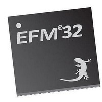
EFM32TG210F32 Energy Micro, EFM32TG210F32 Datasheet - Page 130

EFM32TG210F32
Manufacturer Part Number
EFM32TG210F32
Description
MCU 32BIT 32KB FLASH 32-QFN
Manufacturer
Energy Micro
Series
Tiny Geckor
Specifications of EFM32TG210F32
Core Processor
ARM® Cortex-M3™
Core Size
32-Bit
Speed
32MHz
Connectivity
EBI/EMI, I²C, IrDA, SmartCard, SPI, UART/USART
Peripherals
Brown-out Detect/Reset, DMA, POR, PWM, WDT
Number Of I /o
24
Program Memory Size
32KB (32K x 8)
Program Memory Type
FLASH
Ram Size
4K x 8
Voltage - Supply (vcc/vdd)
1.8 V ~ 3.8 V
Data Converters
A/D 4x12b, D/A 1x12b
Oscillator Type
External
Operating Temperature
-40°C ~ 85°C
Package / Case
32-VQFN Exposed Pad
Processor Series
EFM32
Core
ARM Cortex-M3
Data Bus Width
32 bit
Data Ram Size
32 KB
Interface Type
UART, I2C, SPI
Maximum Clock Frequency
32 MHz
Number Of Programmable I/os
17
Number Of Timers
1
Operating Supply Voltage
1.8 V to 3.8 V
Maximum Operating Temperature
+ 85 C
Mounting Style
SMD/SMT
Processor To Be Evaluated
EFM32TG210
Lead Free Status / RoHS Status
Lead free / RoHS Compliant
Eeprom Size
-
Lead Free Status / Rohs Status
Details
- Current page: 130 of 522
- Download datasheet (9Mb)
13 PRS - Peripheral Reflex System
13.1 Introduction
13.2 Features
13.3 Functional Description
2010-12-21 - d0034_Rev0.90
The Peripheral Reflex System (PRS) system is a network which lets the different peripheral module
communicate directly with each other without involving the CPU. Peripheral modules which send out
Reflex signals are called producers. The PRS routes these reflex signals to consumer peripherals which
apply actions depending on the Reflex signals received. The format for the Reflex signals is not given,
but edge triggers and other functionality can be applied by the PRS.
• 8 configurable interconnect channels
• Software controlled channel output
An overview of the PRS module is shown in Figure 13.1 (p. 131) . The PRS contains 8 interconnect
channels, and each of these can select between all the output Reflex signals offered by the producers.
The consumers can then choose which PRS channel to listen to and perform actions based on the Reflex
signals routed through that channel. The Reflex signals can be both pulse signals and level signals.
Synchronous PRS pulses are one HFPERCLK cycle long, and can either be sent out by a producer (e.g.
ADC conversion complete) or be generated from the edge detector in the PRS channel. Level signals
can have an arbitrary waveform (e.g. Timer PWM output).
0 1 2 3
• Each channel can be connected to any producing peripheral
• Consumers can choose which channel to listen to
• Selectable edge detector (Rising, falling and both edges)
• Configurable level
• Triggered pulses
4
Tim er
DMA
ADC
PRS
PRS
Ch
Ch
...the world's most energy friendly microcontrollers
130
What?
The PRS (Peripheral Reflex System)
allows configurable, fast, and autonomous
communication between the peripherals.
Why?
Events and signals from one peripheral
can be used as input signals or triggers by
other peripherals and ensure timing-critical
operation and reduced software overhead.
How?
Without CPU intervention the peripherals can
send Reflex signals (both pulses and level)
to each other in single- or chained steps. The
peripherals can be set up to perform actions
based on the incoming Reflex signals. This
results in improved system performance and
reduced energy consumption.
Quick Facts
www.energymicro.com
Related parts for EFM32TG210F32
Image
Part Number
Description
Manufacturer
Datasheet
Request
R

Part Number:
Description:
KIT STARTER EFM32 GECKO
Manufacturer:
Energy Micro
Datasheet:

Part Number:
Description:
KIT DEV EFM32 GECKO LCD SUPPORT
Manufacturer:
Energy Micro
Datasheet:

Part Number:
Description:
BOARD PROTOTYPING FOR EFM32
Manufacturer:
Energy Micro
Datasheet:

Part Number:
Description:
KIT DEVELOPMENT EFM32 GECKO
Manufacturer:
Energy Micro
Datasheet:

Part Number:
Description:
MCU, MPU & DSP Development Tools TG840 Sample Kit
Manufacturer:
Energy Micro
Datasheet:

Part Number:
Description:
MCU, MPU & DSP Development Tools TG Starter Kit
Manufacturer:
Energy Micro
Datasheet:

Part Number:
Description:
MCU, MPU & DSP Development Tools TG108 Sample Kit
Manufacturer:
Energy Micro

Part Number:
Description:
MCU, MPU & DSP Development Tools TG210 Sample Kit
Manufacturer:
Energy Micro
Datasheet:

Part Number:
Description:
MCU, MPU & DSP Development Tools TG822 Sample Kit
Manufacturer:
Energy Micro
Datasheet:

Part Number:
Description:
MCU, MPU & DSP Development Tools TG230 Sample Kit
Manufacturer:
Energy Micro

Part Number:
Description:
SAMPLE KIT (SMALL BOX - CONTAINING 2 DEVICES)
Manufacturer:
Energy Micro

Part Number:
Description:
SAMPLE KIT (SMALL BOX - CONTAINING 2 DEVICES)
Manufacturer:
Energy Micro


