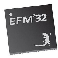
EFM32TG210F32 Energy Micro, EFM32TG210F32 Datasheet - Page 336

EFM32TG210F32
Manufacturer Part Number
EFM32TG210F32
Description
MCU 32BIT 32KB FLASH 32-QFN
Manufacturer
Energy Micro
Series
Tiny Geckor
Specifications of EFM32TG210F32
Core Processor
ARM® Cortex-M3™
Core Size
32-Bit
Speed
32MHz
Connectivity
EBI/EMI, I²C, IrDA, SmartCard, SPI, UART/USART
Peripherals
Brown-out Detect/Reset, DMA, POR, PWM, WDT
Number Of I /o
24
Program Memory Size
32KB (32K x 8)
Program Memory Type
FLASH
Ram Size
4K x 8
Voltage - Supply (vcc/vdd)
1.8 V ~ 3.8 V
Data Converters
A/D 4x12b, D/A 1x12b
Oscillator Type
External
Operating Temperature
-40°C ~ 85°C
Package / Case
32-VQFN Exposed Pad
Processor Series
EFM32
Core
ARM Cortex-M3
Data Bus Width
32 bit
Data Ram Size
32 KB
Interface Type
UART, I2C, SPI
Maximum Clock Frequency
32 MHz
Number Of Programmable I/os
17
Number Of Timers
1
Operating Supply Voltage
1.8 V to 3.8 V
Maximum Operating Temperature
+ 85 C
Mounting Style
SMD/SMT
Processor To Be Evaluated
EFM32TG210
Lead Free Status / RoHS Status
Lead free / RoHS Compliant
Eeprom Size
-
Lead Free Status / Rohs Status
Details
- Current page: 336 of 522
- Download datasheet (9Mb)
21.5.2 LESENSE_TIMCTRL - Timing Control Register (Async Reg)
7:6
5
4:2
1:0
31:24
23:22
21:20
19:12
11
Bit
Offset
0x004
Reset
Access
Name
Bit
2010-12-21 - d0034_Rev0.90
For more information about Asynchronous Registers please see Section 5.3 (p. 18) .
SCANCONF
These bits control which CHx_CONF registers to be used.
Reserved
PRSSEL
Select PRS source for scan start if SCANMODE is set to PRS.
SCANMODE
These bits control how the scan frequency is decided
Reserved
STARTDLY
Delay sensor interaction STARTDELAY LFACLK
Reserved
PCTOP
These bits contain the top value for the period counter.
Reserved
Name
Name
Value
0
1
2
3
Value
0
1
2
3
4
5
6
7
Value
0
1
2
Mode
DIRMAP
INVMAP
TOGGLE
DECDEF
Mode
PRSCH0
PRSCH1
PRSCH2
PRSCH3
PRSCH4
PRSCH5
PRSCH6
PRSCH7
Mode
PERIODIC
ONESHOT
PRS
0x0
0x0
0x0
0x0
0x00
Reset
To ensure compatibility with future devices, always write bits to 0. More information in Section 2.1 (p. 3)
Reset
To ensure compatibility with future devices, always write bits to 0. More information in Section 2.1 (p. 3)
To ensure compatibility with future devices, always write bits to 0. More information in Section 2.1 (p. 3)
To ensure compatibility with future devices, always write bits to 0. More information in Section 2.1 (p. 3)
RW
RW
RW
RW
RW
Access
Access
LESENSE
Description
The channel configuration register registers used are directly mapped to the channel
number.
The channel configuration register registers used are CH
and CH
The channel configuration register registers used toggles between CH
CH
The decoder state defines the CONF registers to be used.
Description
PRS Channel 0 selected as input
PRS Channel 1 selected as input
PRS Channel 2 selected as input
PRS Channel 3 selected as input
PRS Channel 4 selected as input
PRS Channel 5 selected as input
PRS Channel 6 selected as input
PRS Channel 7 selected as input
Description
A new scan is started each time the period counter overflows
A single scan is performed when START in CMD is set
Pulse on PRS channel
...the world's most energy friendly microcontrollers
cycles for each channel
336
X+8
Bit Position
_CONF when channel x triggers
Select scan configuration
Scan start PRS select
Configure scan mode
Start delay configuration
Period counter top value
Description
Description
X-8
_CONF for channels 8-15.
www.energymicro.com
X+8
_CONF for channels 0-7
X
_CONF and
Related parts for EFM32TG210F32
Image
Part Number
Description
Manufacturer
Datasheet
Request
R

Part Number:
Description:
KIT STARTER EFM32 GECKO
Manufacturer:
Energy Micro
Datasheet:

Part Number:
Description:
KIT DEV EFM32 GECKO LCD SUPPORT
Manufacturer:
Energy Micro
Datasheet:

Part Number:
Description:
BOARD PROTOTYPING FOR EFM32
Manufacturer:
Energy Micro
Datasheet:

Part Number:
Description:
KIT DEVELOPMENT EFM32 GECKO
Manufacturer:
Energy Micro
Datasheet:

Part Number:
Description:
MCU, MPU & DSP Development Tools TG840 Sample Kit
Manufacturer:
Energy Micro
Datasheet:

Part Number:
Description:
MCU, MPU & DSP Development Tools TG Starter Kit
Manufacturer:
Energy Micro
Datasheet:

Part Number:
Description:
MCU, MPU & DSP Development Tools TG108 Sample Kit
Manufacturer:
Energy Micro

Part Number:
Description:
MCU, MPU & DSP Development Tools TG210 Sample Kit
Manufacturer:
Energy Micro
Datasheet:

Part Number:
Description:
MCU, MPU & DSP Development Tools TG822 Sample Kit
Manufacturer:
Energy Micro
Datasheet:

Part Number:
Description:
MCU, MPU & DSP Development Tools TG230 Sample Kit
Manufacturer:
Energy Micro

Part Number:
Description:
SAMPLE KIT (SMALL BOX - CONTAINING 2 DEVICES)
Manufacturer:
Energy Micro

Part Number:
Description:
SAMPLE KIT (SMALL BOX - CONTAINING 2 DEVICES)
Manufacturer:
Energy Micro


