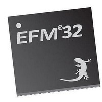
EFM32TG210F32 Energy Micro, EFM32TG210F32 Datasheet - Page 516

EFM32TG210F32
Manufacturer Part Number
EFM32TG210F32
Description
MCU 32BIT 32KB FLASH 32-QFN
Manufacturer
Energy Micro
Series
Tiny Geckor
Specifications of EFM32TG210F32
Core Processor
ARM® Cortex-M3™
Core Size
32-Bit
Speed
32MHz
Connectivity
EBI/EMI, I²C, IrDA, SmartCard, SPI, UART/USART
Peripherals
Brown-out Detect/Reset, DMA, POR, PWM, WDT
Number Of I /o
24
Program Memory Size
32KB (32K x 8)
Program Memory Type
FLASH
Ram Size
4K x 8
Voltage - Supply (vcc/vdd)
1.8 V ~ 3.8 V
Data Converters
A/D 4x12b, D/A 1x12b
Oscillator Type
External
Operating Temperature
-40°C ~ 85°C
Package / Case
32-VQFN Exposed Pad
Processor Series
EFM32
Core
ARM Cortex-M3
Data Bus Width
32 bit
Data Ram Size
32 KB
Interface Type
UART, I2C, SPI
Maximum Clock Frequency
32 MHz
Number Of Programmable I/os
17
Number Of Timers
1
Operating Supply Voltage
1.8 V to 3.8 V
Maximum Operating Temperature
+ 85 C
Mounting Style
SMD/SMT
Processor To Be Evaluated
EFM32TG210
Lead Free Status / RoHS Status
Lead free / RoHS Compliant
Eeprom Size
-
Lead Free Status / Rohs Status
Details
- Current page: 516 of 522
- Download datasheet (9Mb)
...the world's most energy friendly microcontrollers
17.1. TIMER Block Overview ....................................................................................................................... 246
17.2. TIMER Hardware Timer/Counter Control ................................................................................................ 247
17.3. TIMER Clock Selection ....................................................................................................................... 247
17.4. TIMER Connections ........................................................................................................................... 248
17.5. TIMER TOP Value Update Functionality ................................................................................................. 248
17.6. TIMER Quadrature Encoded Inputs ....................................................................................................... 249
17.7. TIMER Quadrature Decoder Configuration .............................................................................................. 249
17.8. TIMER X2 Decoding Mode .................................................................................................................. 250
17.9. TIMER X4 Decoding Mode .................................................................................................................. 250
17.10. TIMER Input Pin Logic ...................................................................................................................... 251
17.11. TIMER Input Capture Buffer Functionality ............................................................................................. 251
17.12. TIMER Output Compare/PWM Buffer Functionality ................................................................................. 252
17.13. TIMER Input Capture ........................................................................................................................ 252
17.14. TIMER Period and/or Pulse width Capture ............................................................................................ 253
17.15. TIMER Block Diagram Showing Comparison Functionality ........................................................................ 253
17.16. TIMER Output Logic ......................................................................................................................... 254
17.17. TIMER Up-count Frequency Generation ............................................................................................... 254
17.18. TIMER Up-count PWM Generation ...................................................................................................... 254
17.19. TIMER CC out in 2x mode ................................................................................................................ 255
17.20. TIMER Up/Down-count PWM Generation .............................................................................................. 256
17.21. TIMER CC out in 2x mode ................................................................................................................ 256
18.1. RTC Overview ................................................................................................................................... 272
19.1. LETIMER Overview ............................................................................................................................ 281
19.2. LETIMER State Machine for Free-running Mode ...................................................................................... 283
19.3. LETIMER One-shot Repeat State Machine ............................................................................................. 284
19.4. LETIMER Buffered Repeat State Machine .............................................................................................. 285
19.5. LETIMER Double Repeat State Machine ................................................................................................ 286
19.6. LETIMER Simple Waveforms Output ..................................................................................................... 288
19.7. LETIMER Repeated Counting .............................................................................................................. 288
19.8. LETIMER Dual Output ........................................................................................................................ 288
19.9. LETIMER Triggered Operation ............................................................................................................. 289
19.10. LETIMER Continuous Operation ......................................................................................................... 290
19.11. LETIMER LETIMERn_CNT Not Initialized to 0 ....................................................................................... 291
20.1. PCNT Overview ................................................................................................................................. 303
20.2. PCNT Quadrature Coding ................................................................................................................... 304
20.3. PCNT Direction Change Interrupt (DIRCNG) Generation ........................................................................... 307
21.1. LESENSE block diagram ..................................................................................................................... 318
21.2. Scan sequence ................................................................................................................................. 320
21.3. Timing diagram, short excitation ........................................................................................................... 320
21.4. Pin sequencing .................................................................................................................................. 322
21.5. Scan result and interrupt generation ...................................................................................................... 323
21.6. Sensor scan and decode sequence ...................................................................................................... 323
21.7. Decoder state transition evaluation ........................................................................................................ 324
21.8. Decoder hysteresis ............................................................................................................................ 325
21.9. Circular result buffer ........................................................................................................................... 326
21.10. Capacitive sense setup ..................................................................................................................... 328
21.11. LC sensor setup .............................................................................................................................. 328
21.12. LC sensor oscillations ....................................................................................................................... 329
21.13. FSM example 1 ............................................................................................................................... 329
21.14. FSM example 2 ............................................................................................................................... 330
22.1. ACMP Overview ................................................................................................................................ 364
22.2. 20 mV Hysteresis Selected .................................................................................................................. 366
22.3. Capacitive Sensing Set-up ................................................................................................................... 367
23.1. VCMP Overview ................................................................................................................................ 375
23.2. VCMP 20 mV Hysteresis Enabled ......................................................................................................... 376
24.1. ADC Overview .................................................................................................................................. 384
24.2. ADC Conversion Timing ...................................................................................................................... 385
24.3. ADC RC Input Filter Configuration ........................................................................................................ 386
24.4. ADC Bias Programming ...................................................................................................................... 387
24.5. ADC Conversion Tailgating .................................................................................................................. 388
25.1. DAC Overview .................................................................................................................................. 406
25.2. DAC Bias Programming ...................................................................................................................... 408
25.3. DAC Sine Mode ................................................................................................................................ 409
26.1. OPAMP System Overview ................................................................................................................... 427
26.2. OPAMP Overview .............................................................................................................................. 428
26.3. Voltage Follower Unity Gain Overview ................................................................................................... 430
26.4. Inverting input PGA Overview .............................................................................................................. 430
26.5. Non-inverting PGA Overview ................................................................................................................ 431
26.6. Cascaded Inverting PGA Overview ....................................................................................................... 431
26.7. Cascaded Non-inverting PGA Overview ................................................................................................. 432
26.8. Two Op-amp Differential Amplifier Overview ........................................................................................... 433
26.9. Three Op-amp Differential Amplifier Overview ......................................................................................... 433
26.10. Dual Buffer ADC Driver Overview ....................................................................................................... 434
27.1. AES Key and Data Definitions .............................................................................................................. 436
www.energymicro.com
2010-12-21 - d0034_Rev0.90
516
Related parts for EFM32TG210F32
Image
Part Number
Description
Manufacturer
Datasheet
Request
R

Part Number:
Description:
KIT STARTER EFM32 GECKO
Manufacturer:
Energy Micro
Datasheet:

Part Number:
Description:
KIT DEV EFM32 GECKO LCD SUPPORT
Manufacturer:
Energy Micro
Datasheet:

Part Number:
Description:
BOARD PROTOTYPING FOR EFM32
Manufacturer:
Energy Micro
Datasheet:

Part Number:
Description:
KIT DEVELOPMENT EFM32 GECKO
Manufacturer:
Energy Micro
Datasheet:

Part Number:
Description:
MCU, MPU & DSP Development Tools TG840 Sample Kit
Manufacturer:
Energy Micro
Datasheet:

Part Number:
Description:
MCU, MPU & DSP Development Tools TG Starter Kit
Manufacturer:
Energy Micro
Datasheet:

Part Number:
Description:
MCU, MPU & DSP Development Tools TG108 Sample Kit
Manufacturer:
Energy Micro

Part Number:
Description:
MCU, MPU & DSP Development Tools TG210 Sample Kit
Manufacturer:
Energy Micro
Datasheet:

Part Number:
Description:
MCU, MPU & DSP Development Tools TG822 Sample Kit
Manufacturer:
Energy Micro
Datasheet:

Part Number:
Description:
MCU, MPU & DSP Development Tools TG230 Sample Kit
Manufacturer:
Energy Micro

Part Number:
Description:
SAMPLE KIT (SMALL BOX - CONTAINING 2 DEVICES)
Manufacturer:
Energy Micro

Part Number:
Description:
SAMPLE KIT (SMALL BOX - CONTAINING 2 DEVICES)
Manufacturer:
Energy Micro


