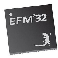
EFM32TG210F32 Energy Micro, EFM32TG210F32 Datasheet - Page 195

EFM32TG210F32
Manufacturer Part Number
EFM32TG210F32
Description
MCU 32BIT 32KB FLASH 32-QFN
Manufacturer
Energy Micro
Series
Tiny Geckor
Specifications of EFM32TG210F32
Core Processor
ARM® Cortex-M3™
Core Size
32-Bit
Speed
32MHz
Connectivity
EBI/EMI, I²C, IrDA, SmartCard, SPI, UART/USART
Peripherals
Brown-out Detect/Reset, DMA, POR, PWM, WDT
Number Of I /o
24
Program Memory Size
32KB (32K x 8)
Program Memory Type
FLASH
Ram Size
4K x 8
Voltage - Supply (vcc/vdd)
1.8 V ~ 3.8 V
Data Converters
A/D 4x12b, D/A 1x12b
Oscillator Type
External
Operating Temperature
-40°C ~ 85°C
Package / Case
32-VQFN Exposed Pad
Processor Series
EFM32
Core
ARM Cortex-M3
Data Bus Width
32 bit
Data Ram Size
32 KB
Interface Type
UART, I2C, SPI
Maximum Clock Frequency
32 MHz
Number Of Programmable I/os
17
Number Of Timers
1
Operating Supply Voltage
1.8 V to 3.8 V
Maximum Operating Temperature
+ 85 C
Mounting Style
SMD/SMT
Processor To Be Evaluated
EFM32TG210
Lead Free Status / RoHS Status
Lead free / RoHS Compliant
Eeprom Size
-
Lead Free Status / Rohs Status
Details
- Current page: 195 of 522
- Download datasheet (9Mb)
15.3.5 PRS RX Input
15.3.6 DMA Support
15.3.7 Transmission Delay
2010-12-21 - d0034_Rev0.90
in USARTn_TRIGCTRL is set, and the transmitter is enabled if TXTEN in USARTn_TRIGCTRL is set.
Only one signal input is supported by the USART.
The AUTOTX feature can also be enabled via PRS. If an external SPI device sets a pin high when there is
data to be read from the device, this signal can be routed to the USART through the PRS system and be
used to make the USART clock data out of the external device. If AUTOTXTEN in USARTn_TRIGCTRL
is set, the USART will transmit data whenever the PRS signal selected by TSEL is high given that there
is enough room in the RX buffer for the chosen frame size. Note that if there is no data in the TX buffer
when using AUTOTX, the TX underflow interrupt will be set.
AUTOTXTEN can also be combined with TXTEN to make the USART transmit a command to the
external device prior to clocking out data. To do this, disable TX using the TXDIS command, load the
TX buffer with the command and enable AUTOTXTEN and TXTEN. When the selected PRS input goes
high, the USART will now transmit the loaded command, and then continue clocking out while both the
PRS input is high and there is room in the RX buffer
The USART can be configured to receive data directly from a PRS channel by setting RXPRS in
USARTn_INPUT. The PRS channel used is selected using RXPRSSEL in USARTn_INPUT. This way,
for example, a differential RX signal can be input to the ACMP and the output routed via PRS to the
USART.
The USART has full DMA support. The DMA controller can write to the transmit buffer using the
registers USARTn_TXDATA, USARTn_TXDATAX, USARTn_TXDOUBLE and USARTn_TXDOUBLEX,
and it can read from the receive buffer using the registers USARTn_RXDATA, USARTn_RXDATAX,
USARTn_RXDOUBLE and USARTn_RXDOUBLEX. This enables single byte transfers, 9 bit data +
control/status bits, double byte and double byte + control/status transfers both to and from the USART.
A request for the DMA controller to read from the USART receive buffer can come from the following
source:
• Data available in the receive buffer
• Data available in the receive buffer and data is for the RIGHT I2S channel. Only used in I2S mode.
A write request can come from one of the following sources:
• Transmit buffer and shift register empty. No data to send.
• Transmit buffer has room for more data
• Transmit buffer has room for RIGHT I2S data. Only used in I2S mode
Even though there are two sources for write requests to the DMA, only one should be used at a time,
since the requests from both sources are cleared even though only one of the requests are used.
In some cases, it may be sensible to temporarily stop DMA access to the USART when an error such
as a framing error has occurred. This is enabled by setting ERRSDMA in USARTn_CTRL.
By configuring TXDELAY in USARTn_CTRL, the transmitter can be forced to wait a number of bit-
periods from it is ready to transmit data, to it actually transmits the data. This delay is only applied to the
first frame transmitted after the transmitter has been idle. When transmitting frames back-to-back the
delay is not introduced between the transmitted frames.
This is useful on half duplex buses, because the receiver always returns received frames to software
during the first stop-bit. The bus may still be driven for up to 3 baud periods, depending on the current
...the world's most energy friendly microcontrollers
195
www.energymicro.com
Related parts for EFM32TG210F32
Image
Part Number
Description
Manufacturer
Datasheet
Request
R

Part Number:
Description:
KIT STARTER EFM32 GECKO
Manufacturer:
Energy Micro
Datasheet:

Part Number:
Description:
KIT DEV EFM32 GECKO LCD SUPPORT
Manufacturer:
Energy Micro
Datasheet:

Part Number:
Description:
BOARD PROTOTYPING FOR EFM32
Manufacturer:
Energy Micro
Datasheet:

Part Number:
Description:
KIT DEVELOPMENT EFM32 GECKO
Manufacturer:
Energy Micro
Datasheet:

Part Number:
Description:
MCU, MPU & DSP Development Tools TG840 Sample Kit
Manufacturer:
Energy Micro
Datasheet:

Part Number:
Description:
MCU, MPU & DSP Development Tools TG Starter Kit
Manufacturer:
Energy Micro
Datasheet:

Part Number:
Description:
MCU, MPU & DSP Development Tools TG108 Sample Kit
Manufacturer:
Energy Micro

Part Number:
Description:
MCU, MPU & DSP Development Tools TG210 Sample Kit
Manufacturer:
Energy Micro
Datasheet:

Part Number:
Description:
MCU, MPU & DSP Development Tools TG822 Sample Kit
Manufacturer:
Energy Micro
Datasheet:

Part Number:
Description:
MCU, MPU & DSP Development Tools TG230 Sample Kit
Manufacturer:
Energy Micro

Part Number:
Description:
SAMPLE KIT (SMALL BOX - CONTAINING 2 DEVICES)
Manufacturer:
Energy Micro

Part Number:
Description:
SAMPLE KIT (SMALL BOX - CONTAINING 2 DEVICES)
Manufacturer:
Energy Micro


