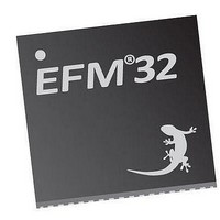
EFM32TG210F32 Energy Micro, EFM32TG210F32 Datasheet - Page 407

EFM32TG210F32
Manufacturer Part Number
EFM32TG210F32
Description
MCU 32BIT 32KB FLASH 32-QFN
Manufacturer
Energy Micro
Series
Tiny Geckor
Specifications of EFM32TG210F32
Core Processor
ARM® Cortex-M3™
Core Size
32-Bit
Speed
32MHz
Connectivity
EBI/EMI, I²C, IrDA, SmartCard, SPI, UART/USART
Peripherals
Brown-out Detect/Reset, DMA, POR, PWM, WDT
Number Of I /o
24
Program Memory Size
32KB (32K x 8)
Program Memory Type
FLASH
Ram Size
4K x 8
Voltage - Supply (vcc/vdd)
1.8 V ~ 3.8 V
Data Converters
A/D 4x12b, D/A 1x12b
Oscillator Type
External
Operating Temperature
-40°C ~ 85°C
Package / Case
32-VQFN Exposed Pad
Processor Series
EFM32
Core
ARM Cortex-M3
Data Bus Width
32 bit
Data Ram Size
32 KB
Interface Type
UART, I2C, SPI
Maximum Clock Frequency
32 MHz
Number Of Programmable I/os
17
Number Of Timers
1
Operating Supply Voltage
1.8 V to 3.8 V
Maximum Operating Temperature
+ 85 C
Mounting Style
SMD/SMT
Processor To Be Evaluated
EFM32TG210
Lead Free Status / RoHS Status
Lead free / RoHS Compliant
Eeprom Size
-
Lead Free Status / Rohs Status
Details
- Current page: 407 of 522
- Download datasheet (9Mb)
25.3.1.5 Clock Prescaling
25.3.2 Reference Selection
25.3.3 Programming of Bias Current
2010-12-21 - d0034_Rev0.90
If the PRSEN bit in DACn_CHxCTRL is set, a DAC conversion on channel x will not be started by data
write, but when a positive one HFPERCLK cycle pulse is received on the PRS input selected by PRSSEL
in DACn_CHxCTRL.
The CH0DV and CH1DV bits in DACn_STATUS indicate that the corresponding channel contains data
that has not yet been converted.
When entering Energy Mode 4, both DAC channels must be stopped.
The DAC has an internal clock prescaler, which can divide the HFPERCLK by any factor between 1 and
128, by setting the PRESC bits in DACnCTRL. The resulting DAC_CLK is used by the converter core
and the frequency is given by Equation 25.1 (p. 407) :
DAC Clock Prescaling
where f
DAC_CLK should not be set higher than 1 MHz.
Normally the PRESCALER runs continuously when either of the channels are enabled. When running
with a prescaler setting higher than 0, there will be an unpredictable delay from the time the conversion
was triggered to the time the actual conversion takes place. This is because the conversions is controlled
by the prescaled clock and the conversion can arrive at any time during a prescaled clock (DAC_CLK)
period. However, if the CH0PRESCRST bit in DACn_CTRL is set, the prescaler will be reset every time
a conversion is triggered on channel 0. This leads to a predictable latency between channel 0 trigger
and conversion.
Three internal voltage references are available and are selected by setting the REFSEL bits in
DACn_CTRL:
• Internal 2.5V
• Internal 1.25V
• V
The reference selection can only be changed while both channels are disabled. The references for the
DAC need to be enabled for some time before they can be used. This is called the warm-up period, and
starts when one of the channels is enabled. For a bandgap reference, this period is 5 DAC_CLK cycles
while the V
the prescaler is set correctly) and delay any conversion triggers received during the warm-up until the
references have stabilized.
The bias current of the bandgap reference and the DAC output buffer can be scaled by the BIASPROG
and HALFBIAS bit fields of the DACn_BIASPROG register as illustrated in Figure 25.2 (p. 408) .
DD
HFPERCLK
DD
reference needs 1 DAC_CLK cycle. The DAC will time this period automatically(given that
is the HFPERCLK frequency. One conversion takes 2 DAC_CLK cycles and the
f
DAC_CLK
= f
HFPERCLK
...the world's most energy friendly microcontrollers
407
/ 2 ^ PRESC
www.energymicro.com
(25.1)
Related parts for EFM32TG210F32
Image
Part Number
Description
Manufacturer
Datasheet
Request
R

Part Number:
Description:
KIT STARTER EFM32 GECKO
Manufacturer:
Energy Micro
Datasheet:

Part Number:
Description:
KIT DEV EFM32 GECKO LCD SUPPORT
Manufacturer:
Energy Micro
Datasheet:

Part Number:
Description:
BOARD PROTOTYPING FOR EFM32
Manufacturer:
Energy Micro
Datasheet:

Part Number:
Description:
KIT DEVELOPMENT EFM32 GECKO
Manufacturer:
Energy Micro
Datasheet:

Part Number:
Description:
MCU, MPU & DSP Development Tools TG840 Sample Kit
Manufacturer:
Energy Micro
Datasheet:

Part Number:
Description:
MCU, MPU & DSP Development Tools TG Starter Kit
Manufacturer:
Energy Micro
Datasheet:

Part Number:
Description:
MCU, MPU & DSP Development Tools TG108 Sample Kit
Manufacturer:
Energy Micro

Part Number:
Description:
MCU, MPU & DSP Development Tools TG210 Sample Kit
Manufacturer:
Energy Micro
Datasheet:

Part Number:
Description:
MCU, MPU & DSP Development Tools TG822 Sample Kit
Manufacturer:
Energy Micro
Datasheet:

Part Number:
Description:
MCU, MPU & DSP Development Tools TG230 Sample Kit
Manufacturer:
Energy Micro

Part Number:
Description:
SAMPLE KIT (SMALL BOX - CONTAINING 2 DEVICES)
Manufacturer:
Energy Micro

Part Number:
Description:
SAMPLE KIT (SMALL BOX - CONTAINING 2 DEVICES)
Manufacturer:
Energy Micro


