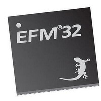
EFM32TG210F32 Energy Micro, EFM32TG210F32 Datasheet - Page 48

EFM32TG210F32
Manufacturer Part Number
EFM32TG210F32
Description
MCU 32BIT 32KB FLASH 32-QFN
Manufacturer
Energy Micro
Series
Tiny Geckor
Specifications of EFM32TG210F32
Core Processor
ARM® Cortex-M3™
Core Size
32-Bit
Speed
32MHz
Connectivity
EBI/EMI, I²C, IrDA, SmartCard, SPI, UART/USART
Peripherals
Brown-out Detect/Reset, DMA, POR, PWM, WDT
Number Of I /o
24
Program Memory Size
32KB (32K x 8)
Program Memory Type
FLASH
Ram Size
4K x 8
Voltage - Supply (vcc/vdd)
1.8 V ~ 3.8 V
Data Converters
A/D 4x12b, D/A 1x12b
Oscillator Type
External
Operating Temperature
-40°C ~ 85°C
Package / Case
32-VQFN Exposed Pad
Processor Series
EFM32
Core
ARM Cortex-M3
Data Bus Width
32 bit
Data Ram Size
32 KB
Interface Type
UART, I2C, SPI
Maximum Clock Frequency
32 MHz
Number Of Programmable I/os
17
Number Of Timers
1
Operating Supply Voltage
1.8 V to 3.8 V
Maximum Operating Temperature
+ 85 C
Mounting Style
SMD/SMT
Processor To Be Evaluated
EFM32TG210
Lead Free Status / RoHS Status
Lead free / RoHS Compliant
Eeprom Size
-
Lead Free Status / Rohs Status
Details
- Current page: 48 of 522
- Download datasheet (9Mb)
8.4.2.3.1 Invalid
8.4.2.3.2 Basic
8.4.2.3.3 Auto-request
2010-12-21 - d0034_Rev0.90
Table 8.3. DMA cycle types
Note
For all cycle types, the controller arbitrates after 2
a large 2
DMA transfer completes. Therefore, you must take care when setting the R_power, that you do not
significantly increase the latency for high-priority channels.
After the controller completes a DMA cycle it sets the cycle type to invalid, to prevent it from repeating
the same DMA cycle.
In this mode, you configure the controller to use either the primary, or alternate, data structure. After you
enable the channel, and the controller receives a request then the flow for this DMA cycle is:
1. The controller performs 2
2. The controller arbitrates:
3. The controller sets dma_done[C] HIGH for one HFCORECLK cycle. This indicates to the host
When the controller operates in this mode, it is only necessary for it to receive a single request to enable
it to complete the entire DMA cycle. This enables a large data transfer to occur, without significantly
increasing the latency for servicing higher priority requests, or requiring multiple requests from the
processor or peripheral.
You can configure the controller to use the primary, or alternate, data structure. After you enable the
channel, and the controller receives a request for this channel, then the flow for this DMA cycle is:
1. The controller performs 2
2. The controller arbitrates. When channel C has the highest priority then the DMA cycle continues at
cycle_ctrl
b000
b001
b010
b011
b100
b101
b110
b111
at step 3 (p. 48) .
• if a higher-priority channel is requesting service then the controller services that channel
• if the peripheral or software signals a request to the controller then it continues at step 1 (p. 48) .
processor that the DMA cycle is complete.
flow continues at step 3 (p. 49) .
step 1 (p. 48) .
R
The cycle_ctrl bits are located in the channel_cfg memory location that Section 8.4.3.3 (p.
58) describes.
value then it prevents all other channels from performing a DMA transfer, until the low-priority
Description
Channel control data structure is invalid
Basic DMA transfer
Auto-request
Ping-pong
Memory scatter-gather using the primary data structure
Memory scatter-gather using the alternate data structure
Peripheral scatter-gather using the primary data structure
Peripheral scatter-gather using the alternate data structure
R
R
transfers. If the number of transfers remaining is zero the flow continues
transfers for channel C. If the number of transfers remaining is zero the
...the world's most energy friendly microcontrollers
48
R
DMA transfers. If you set a low-priority channel with
www.energymicro.com
Related parts for EFM32TG210F32
Image
Part Number
Description
Manufacturer
Datasheet
Request
R

Part Number:
Description:
KIT STARTER EFM32 GECKO
Manufacturer:
Energy Micro
Datasheet:

Part Number:
Description:
KIT DEV EFM32 GECKO LCD SUPPORT
Manufacturer:
Energy Micro
Datasheet:

Part Number:
Description:
BOARD PROTOTYPING FOR EFM32
Manufacturer:
Energy Micro
Datasheet:

Part Number:
Description:
KIT DEVELOPMENT EFM32 GECKO
Manufacturer:
Energy Micro
Datasheet:

Part Number:
Description:
MCU, MPU & DSP Development Tools TG840 Sample Kit
Manufacturer:
Energy Micro
Datasheet:

Part Number:
Description:
MCU, MPU & DSP Development Tools TG Starter Kit
Manufacturer:
Energy Micro
Datasheet:

Part Number:
Description:
MCU, MPU & DSP Development Tools TG108 Sample Kit
Manufacturer:
Energy Micro

Part Number:
Description:
MCU, MPU & DSP Development Tools TG210 Sample Kit
Manufacturer:
Energy Micro
Datasheet:

Part Number:
Description:
MCU, MPU & DSP Development Tools TG822 Sample Kit
Manufacturer:
Energy Micro
Datasheet:

Part Number:
Description:
MCU, MPU & DSP Development Tools TG230 Sample Kit
Manufacturer:
Energy Micro

Part Number:
Description:
SAMPLE KIT (SMALL BOX - CONTAINING 2 DEVICES)
Manufacturer:
Energy Micro

Part Number:
Description:
SAMPLE KIT (SMALL BOX - CONTAINING 2 DEVICES)
Manufacturer:
Energy Micro


