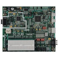
LFEBS12UB Freescale Semiconductor, LFEBS12UB Datasheet - Page 343

LFEBS12UB
Manufacturer Part Number
LFEBS12UB
Description
KIT STUDENT LEARNING S12 DG128
Manufacturer
Freescale Semiconductor
Specifications of LFEBS12UB
Architecture
8/16-bit
Code Gen Tools Included
Code Warrior
Silicon Manufacturer
Freescale
Core Architecture
S12
Core Sub-architecture
S12
Silicon Core Number
MC9S12
Silicon Family Name
S12D
Kit Contents
HCS12 DG128 Learning Kit
Rohs Compliant
Yes
Lead Free Status / RoHS Status
Lead free / RoHS Compliant
- Current page: 343 of 1328
- Download datasheet (9Mb)
The least significant word of each 64-bit wide array line is read out first. This corresponds to the bytes 1
and 0 of
Reading the Trace Buffer while the S12XDBG module is armed will return invalid data and no shifting of
the RAM pointer will occur.
8.4.5.5
The Trace Buffer contents are not initialized by a system reset. Thus should a system reset occur, the trace
session information from immediately before the reset occurred can be read out. The DBGCNT bits are
not cleared by a system reset. Thus should a reset occur, the number of valid lines in the trace buffer is
indicated by DBGCNT. The internal pointer to the current trace buffer address is initialized by unlocking
the trace buffer thus points to the oldest valid data even if a reset occurred during the tracing session.
Generally debugging occurrences of system resets is best handled using mid or end trigger alignment since
the reset may occur before the trace trigger, which in the begin trigger alignment case means no
information would be stored in the trace buffer.
8.4.6
A tag follows program information as it advances through the instruction queue. When a tagged instruction
reaches the head of the queue a tag hit occurs and triggers the state sequencer.
Each comparator control register features a TAG bit, which controls whether the comparator match will
cause a trigger immediately or tag the opcode at the matched address. If a comparator is enabled for tagged
comparisons, the address stored in the comparator match address registers must be an opcode address for
the trigger to occur.
Both CPU12X and XGATE opcodes can be tagged with the comparator register TAG bits.
Using Begin trigger together with tagging, if the tagged instruction is about to be executed then the
transition to the next state sequencer state occurs. If the transition is to the Final State, tracing is started.
Only upon completion of the tracing session can a breakpoint be generated. Similarly using Mid trigger
with tagging, if the tagged instruction is about to be executed then the trace is continued for another 32
lines. Upon tracing completion the breakpoint is generated. Using End trigger, when the tagged instruction
is about to be executed and the next transition is to Final State then a breakpoint is generated immediately,
before the tagged instruction is carried out.
Read/Write (R/W), access size (SZ) monitoring and data bus monitoring is not useful if tagged triggering
is selected, since the tag is attached to the opcode at the matched address and is not dependent on the data
bus nor on the type of access. Thus these bits are ignored if tagged triggering is selected.
When configured for range comparisons and tagging, the ranges are accurate only to word boundaries.
Freescale Semiconductor
Because of an order from the United States International Trade Commission, BGA-packaged product lines and partnumbers
indicated here currently are not available from Freescale for import or sale in the United States prior to September 2010
Table
Tagging
Trace Buffer Reset State
8-43. The bytes containing invalid information (shaded in
An external pin RESET that occurs simultaneous to a trace buffer entry can,
in very seldom cases, lead to either that entry being corrupted or the first
entry of the session being corrupted. In such cases the other contents of the
trace buffer still contain valid tracing information. The case occurs when the
reset assertion coincides with the trace buffer entry clock edge.
MC9S12XE-Family Reference Manual Rev. 1.23
NOTE
Chapter 8 S12X Debug (S12XDBGV3) Module
Table
8-43) are also read out.
343
Related parts for LFEBS12UB
Image
Part Number
Description
Manufacturer
Datasheet
Request
R
Part Number:
Description:
Manufacturer:
Freescale Semiconductor, Inc
Datasheet:
Part Number:
Description:
Manufacturer:
Freescale Semiconductor, Inc
Datasheet:
Part Number:
Description:
Manufacturer:
Freescale Semiconductor, Inc
Datasheet:
Part Number:
Description:
Manufacturer:
Freescale Semiconductor, Inc
Datasheet:
Part Number:
Description:
Manufacturer:
Freescale Semiconductor, Inc
Datasheet:
Part Number:
Description:
Manufacturer:
Freescale Semiconductor, Inc
Datasheet:
Part Number:
Description:
Manufacturer:
Freescale Semiconductor, Inc
Datasheet:
Part Number:
Description:
Manufacturer:
Freescale Semiconductor, Inc
Datasheet:
Part Number:
Description:
Manufacturer:
Freescale Semiconductor, Inc
Datasheet:
Part Number:
Description:
Manufacturer:
Freescale Semiconductor, Inc
Datasheet:
Part Number:
Description:
Manufacturer:
Freescale Semiconductor, Inc
Datasheet:
Part Number:
Description:
Manufacturer:
Freescale Semiconductor, Inc
Datasheet:
Part Number:
Description:
Manufacturer:
Freescale Semiconductor, Inc
Datasheet:
Part Number:
Description:
Manufacturer:
Freescale Semiconductor, Inc
Datasheet:
Part Number:
Description:
Manufacturer:
Freescale Semiconductor, Inc
Datasheet:


